What's New In The 3D Printer World
Tronxy X5S Build
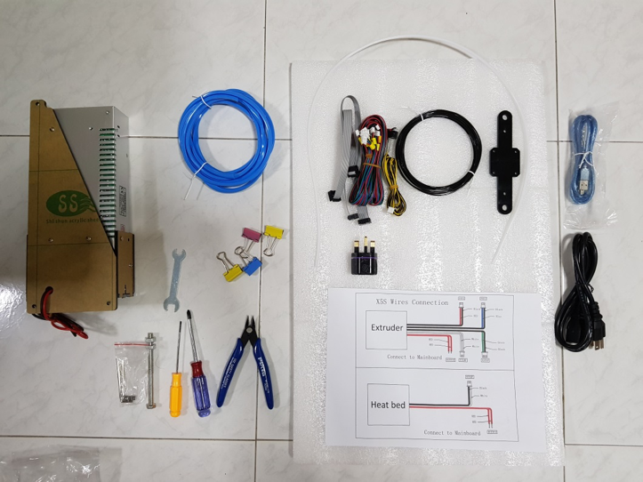
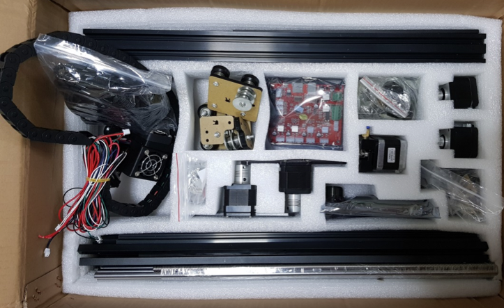
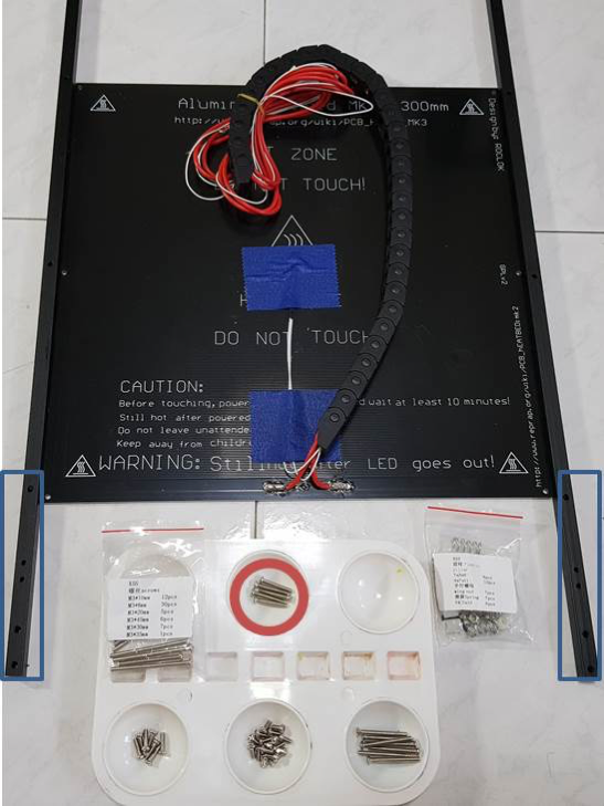
What’s in the box?
Build
General notes:
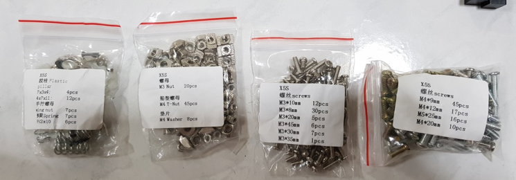
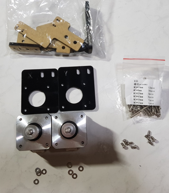
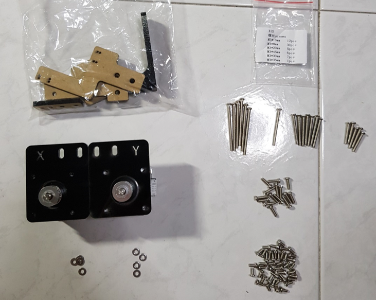
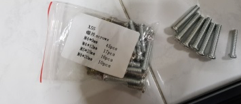
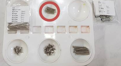
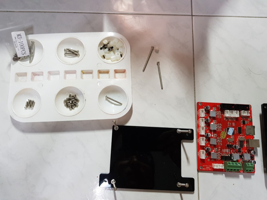
Screws are generally organized into 2 bags – M3 sized and M4 sized of different lengths
I bought a 2 bags of washers, M3 and M4 sized (100pcs per bag), more than enough for the entire build. The washers are handy for places where metal screws come into contact with the acrylic parts.
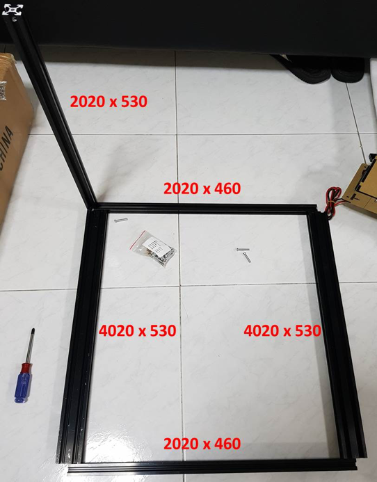
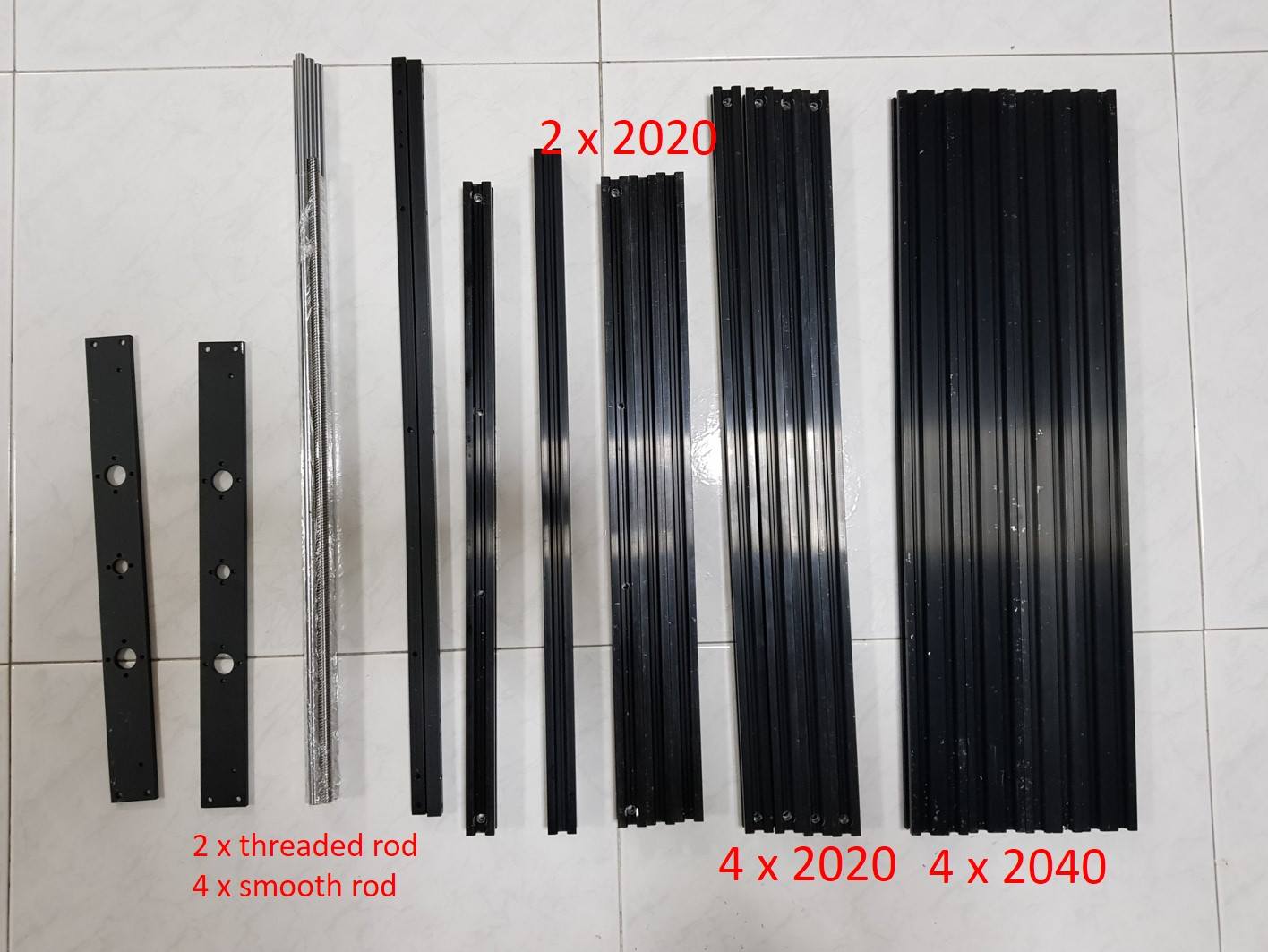
4020 flat on the floor, the shorter 2020 on the floor, the longer 2020s standing up.
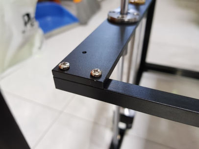
TAKE NOTE: Orientate/Rotate the rods such that the countersunk holes face towards the outside of the frame – this applies to ALL of the rods for the frame. Take a look at the next image for an example.
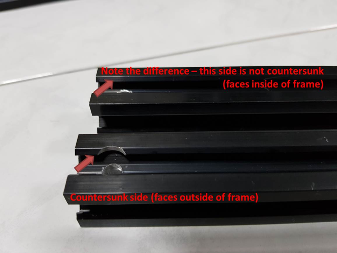
ALL COUNTERSUNK SIDES ON THE ALUMINIUM EXTRUSIONS FACE THE OUTSIDE OF THE FRAME!
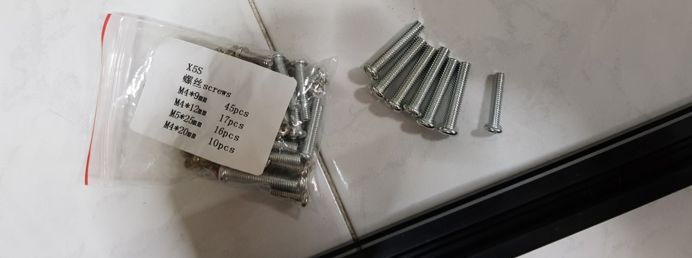
Use the silver (longer) screws from this bag to secure the frame
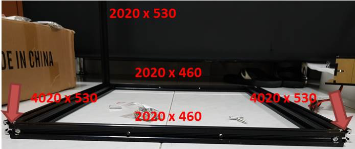
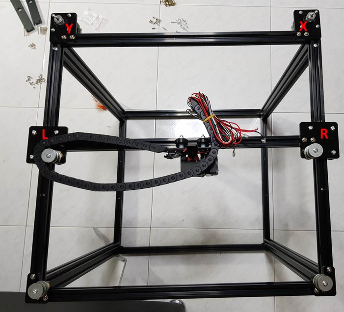
Leave the sides open as per the arrows, screw the 2020 x 460 to the inner side of the 4020 x 530 extrusions
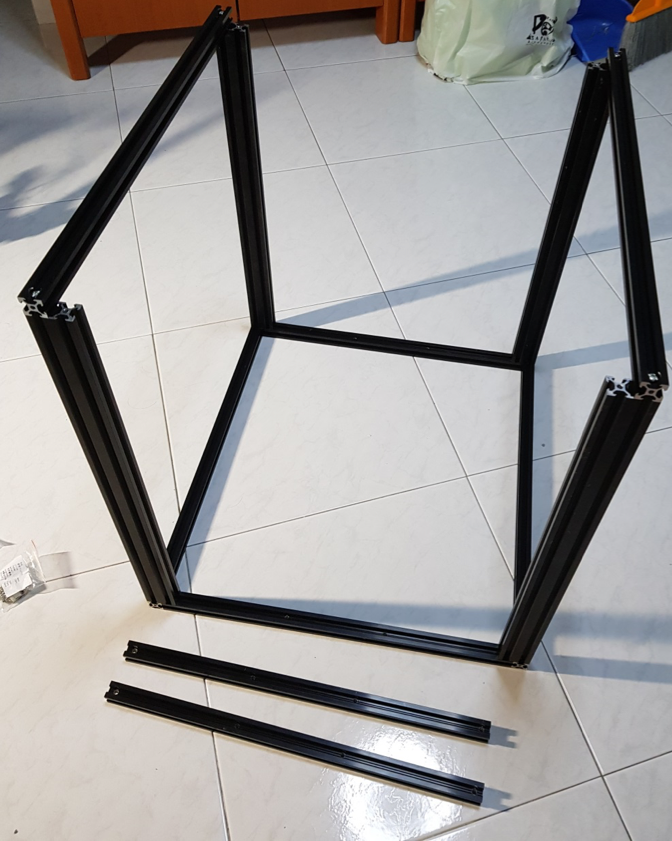
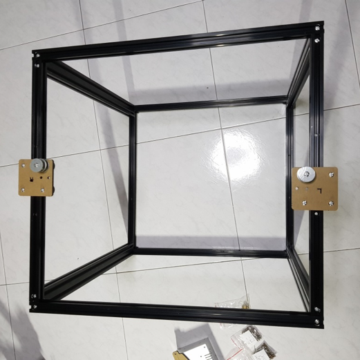
Complete the frame until you get to this stage, leave out 2 x 2020 x 460mm on the top of the frame.
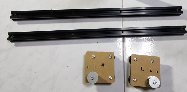
Prepare the following parts
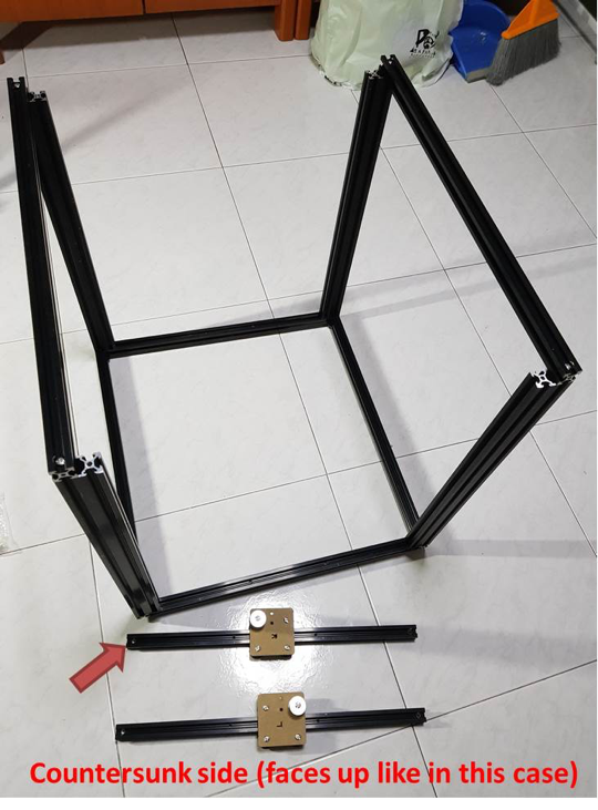
Slide the carriages onto the 2020 x 460 extrusions, make sure the countersunk side is facing up and out as per the photo
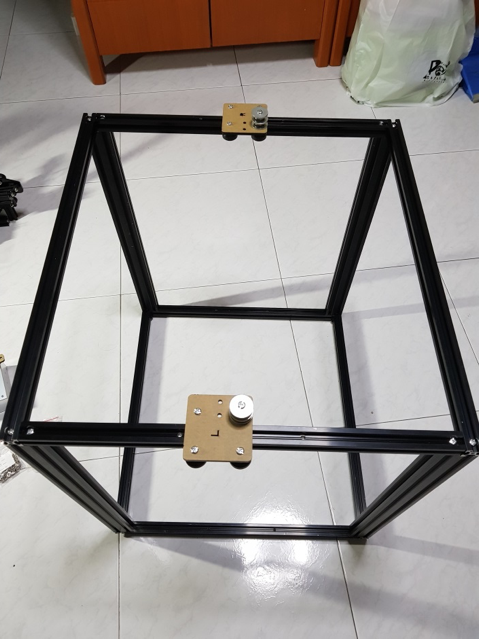
Complete the frame like this.
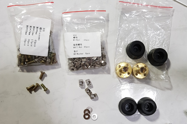
Get the respective screws and T nuts and rubber feet from the above bags:
4 x M4 shortest screw
4x T nuts
4 x Washers
4 x Rubber feet
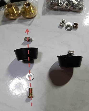
Assemble the rubber feet like so, leave the T nut loose so that we can tighten it against the frame later. You’ll need to do this 4 times. Those who have not had experience with T nuts before, I suggest being familiar with how to use them first, because this build uses countless numbers of T nuts…
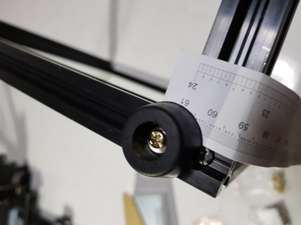
Secure the rubber feet to the bottom of the frame (the side that you mounted the carriages on just now is the top). If you’re anal like me… Measure out 2mm from the edge of the frame to the middle of the rubber feet. Repeat on all 4 corners.
Finished build of the frame! Rubber feet at the bottom, carriages on the top.
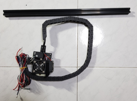
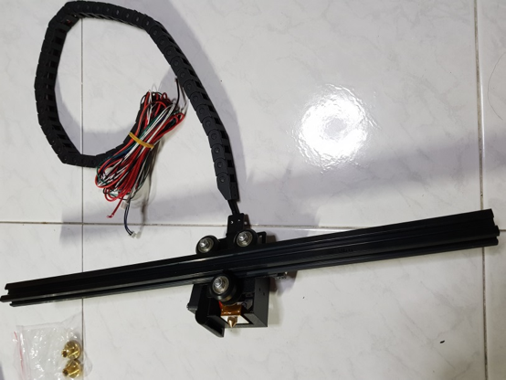
Now for the toolhead. Slide it on the 2020 x 484mm extrusion.
Like this, the orientation of the extrusion doesn’t matter, the sides are all the same.
Tear off the protective paper and insert T nuts into all the holes. Use the shortest M4 screws again. Do the same on both sides.
NOTE: Notice that I have added washers to the places where the screws come into contact with the acrylic pieces. This is to distribute the force over the acrylic more evenly so that I will not crack the plastic even if I tighten a little harder. This is optional, and not a must have, though I recommend it. Recommended sizes to buy are M3 (about 50), M4 (about 50), and M5 (about 5) washers.
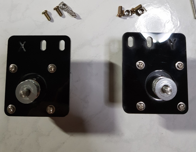
Use the shortest M3 screws in the bag to secure the stepper motors to the acrylic. Again, I have added my own M3 washers, this is optional.
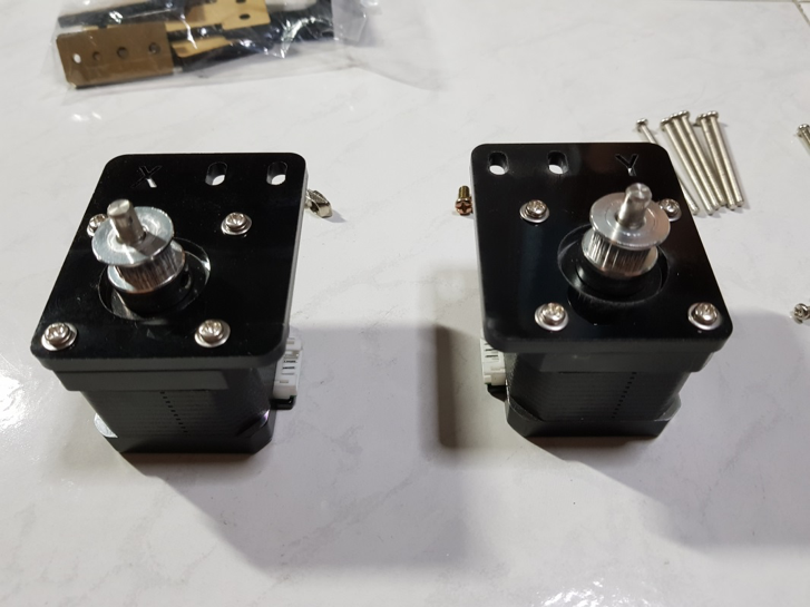
Note the position of the white connectors, they have to be facing exactly as pictured.
Next, add T nuts to the holes at the top, again using the shortest M4 screw in the bag.
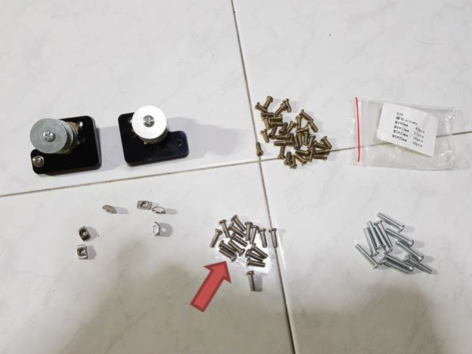
Next, find the above pieces. The acrylic here is slightly thicker, so use the medium sized M4 screws (pointed with the arrow) with the T nuts. Screw the T nuts into all 3 holes on each piece.
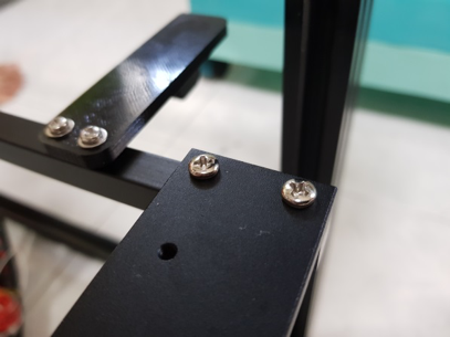
Mount them on the top edges of the frame like so.
Next, slot the toolhead with the 2020 extrusion into the Left and Right carriages, securing the extrusion with the T nuts on the carriages. Mount the motors as pictured too.
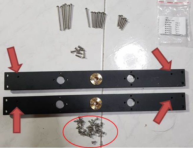
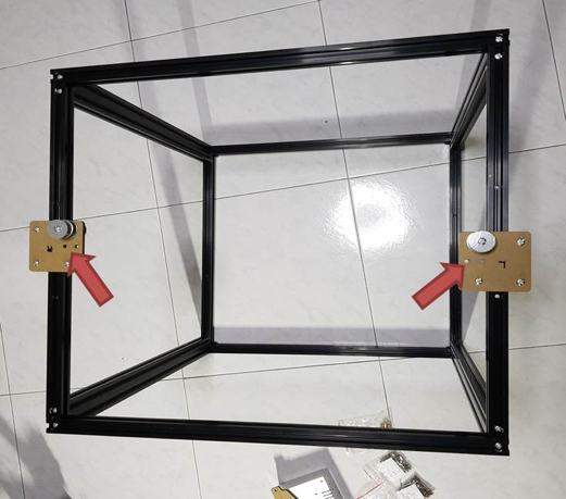
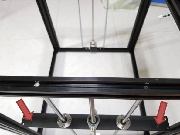
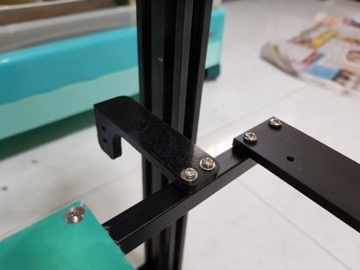
The black aluminium plates pictured here are NOT symmetrical (as indicated by the red arrows, the holes are only on one side of the aluminium), take note of this for now, during the assembly of the plates later, we will have to pay closer attention. (Make sure that the holes as indicated by the arrows are facing outside when installing the aluminium plates later!) For attaching the golden screw, use the smallest M3 screws as circled in the picture.
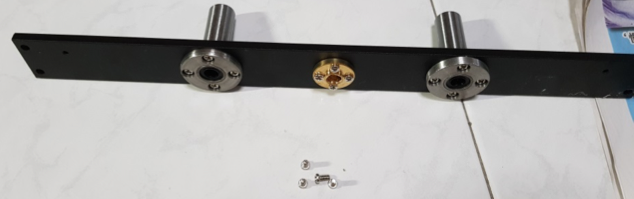
Install the linear bearings with the same screws.
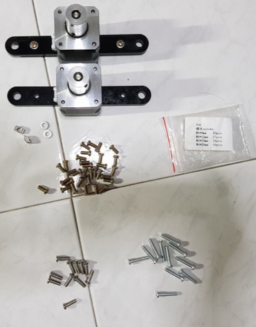
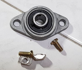
Fix the T nuts onto the 2 x motor mounts and 2 x flange bearings with the shortest M4 screws. Again, washers are my own addition.
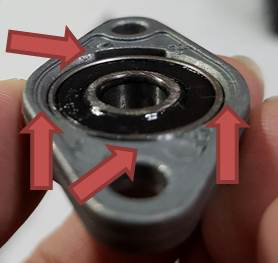
Make sure that the sides of the bearings are flat with the flange! If they are now flush by even a bit, you must flatten it to ensure that the rod can go in perpendicularly to the bearings! This will have implications later in the build and you risk damaging the rods!
Assembled the above parts as shown. Take note, the hole as shown in the photo should be facing the outside of the frame on both sides!
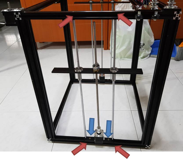
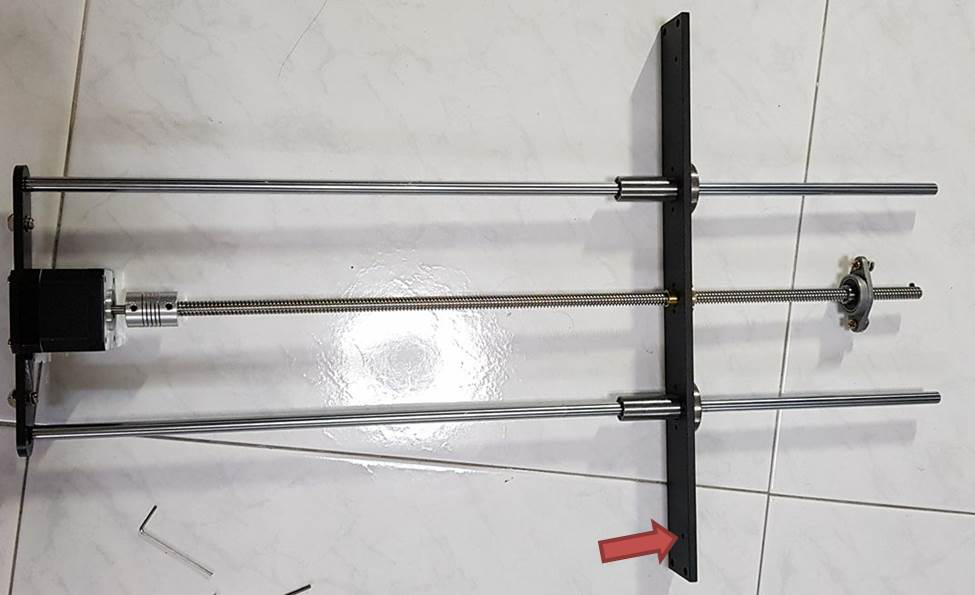
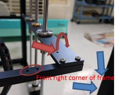
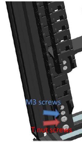
Install the z axis rods and motor on the side of the printer, use the longest M4 screw in the bag to tighten the rods to the frame at the screw holes as indicated by the red arrows. Then tighten the T nuts of the acrylic to the frame (blue arrows). Repeat the procedure on the other side too!
Align the holes of the rod to the top of the frame, make sure that the holes indicated by the red arrows are facing towards the outside of the frame!
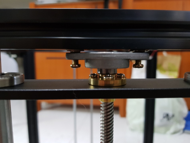
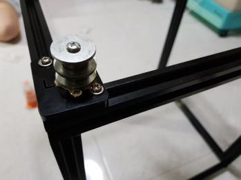
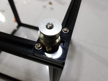
Turn the Z axis motor such that the black aluminium bar is right up top with the flange bearing as shown in the photo.
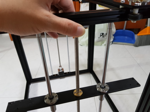
Hold the flange bearing in place firmly with your fingers and lower the black bar by turning the z motor to allow enough space to insert a screwdriver to tighten the T nuts on the flange bearing.
After tightening, turn the Z motor and move the black bar up and down, ensure no binding occurs at any level.
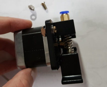
Install T nuts on to the extruder with the shortest M4 screw in the bag.
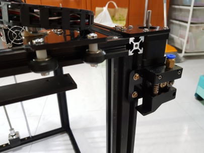
Mount the extruder motor below the X stepper motor like so.
Note: the black rod has two ends, one with more holes and one end with less (marked buy the blue block). Just make sure both ends with more holes (the side marked with the blue box) is on the right side of the frame when installing! See pictures below.
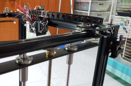
Attach the two rods to the Z bar on both sides with M4 screws (medium length ones) on all four corners.
TAKE NOTE: On both front and back rods, the two holes (as indicated by the red circle) should be on the right side of the frame (the black rod is not symmetrical).
Note that there is a mistake in the picture, the hole on the Z bar (indicated by the red arrow, should be on the outside, i.e. the Z bar should be flipped around. If you follow my instructions previously, this should not happen!)
The pictures here are the back of the frame (back of the frame is the side of the frame with the motor mounted on it. Mount this plastic piece to the black rod with smallest M3 screws in the direction as shown in the photo. There is an error in the mounting of the Z bar in these photos as mentioned previously, it should be flipped around.
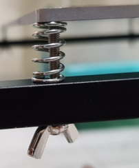
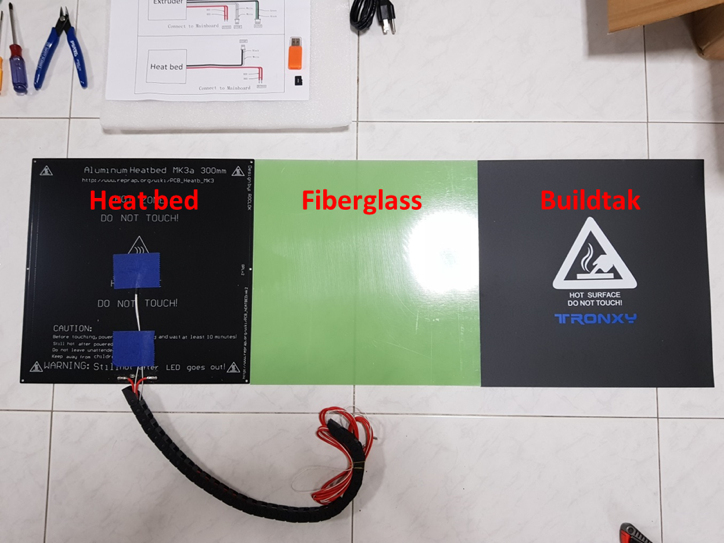
Install the heatbed, wires facing the right. We will be using 6 x K3 30mm screws (circled in red, these are the ones with angled head, not the round head like the ones we used previously). From top to bottom, heatbed, K3 x 30mm screw, spring, black rod, wing nut. Repeat this x 6. The green ?fiberglass sheet goes on top of the heatbed. Secure the green fiberglass sheet with the binder clips provided.
Assemble the spool holder as such. The big bolt through the largest hole in the acrylic, then T nuts on the other two holes. As this plastic piece is thicker, use the medium length M4 screws in the bag.
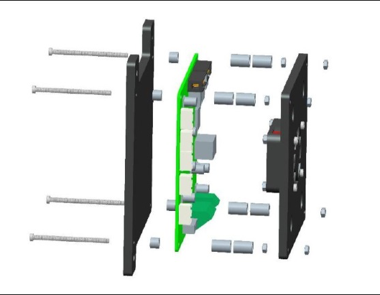
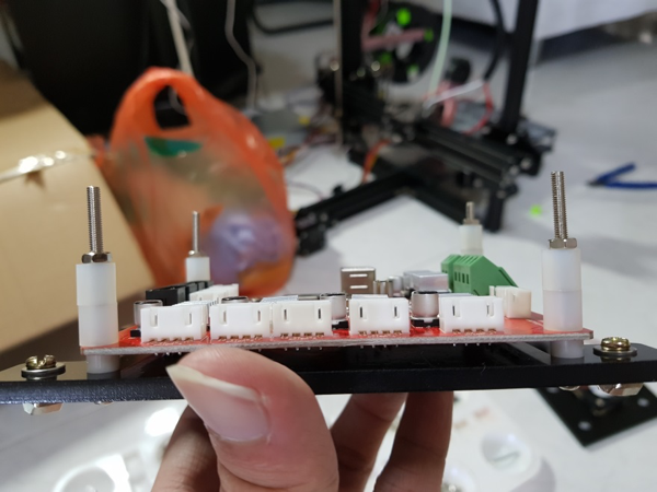
Next we move on to electronics. Use the longest M3 screw, plastic pillars and M3 nut to mount the control board to the black acrylic. Their diagram explains this quite well. Note the acrylic is not symmetrical.
Install T nuts to the 3 corner holes that are larger using the shortest M4 screw.
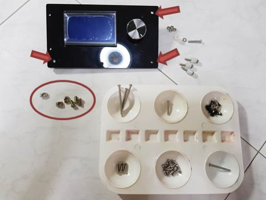
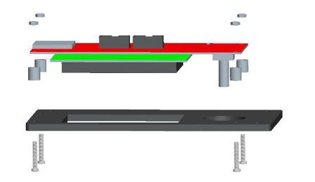
Same thing for the LCD panel, their diagram explains it quite well. Use the medium sized M3 screws with plastic spacers and M3 nuts to attach the LCD to the acrylic. The larger holes indicated by red arrows are for the T nuts with the shortest M4 screws (circled).
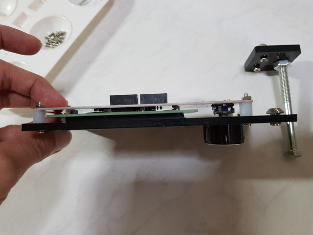
CD assembly should be as such.
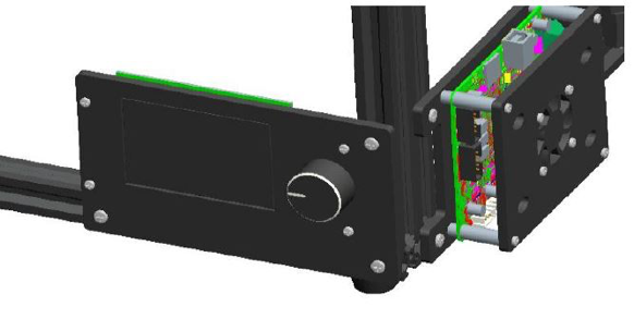
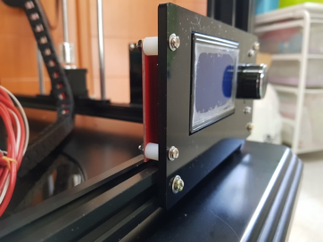
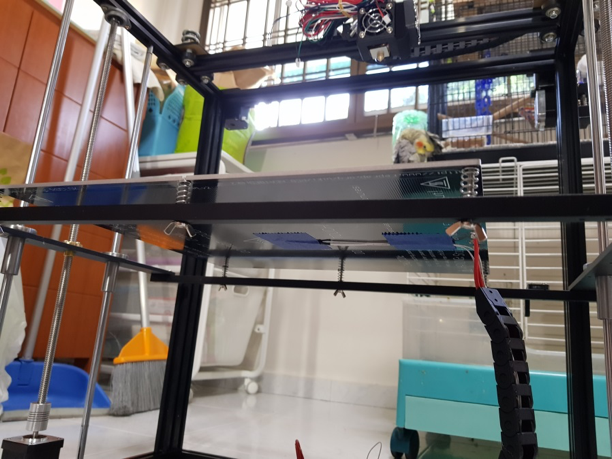
Time to mount everything! LCD at the front right bottom corner of the frame, the control board at the front right side of the frame (perpendicular to the LCD).
Install the cable guard
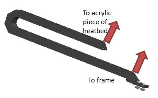
There are two cable guards, one on the back of the printer joining the heatbed to the back of the frame, the other going from the hotend to the back of the frame.
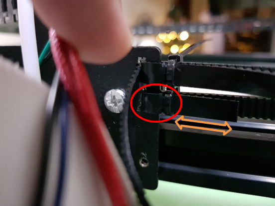
My cable guard came assembled the wrong way. However this is not a problem, just push on both sides of the plastic tab (red arrows) with a screwdriver and the first link should come out. Flip it around and snap it back on. Make sure that the orientation of the two ends looks like that in the photo.
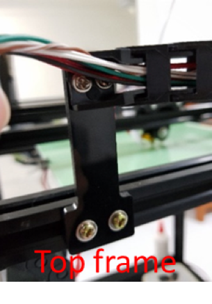
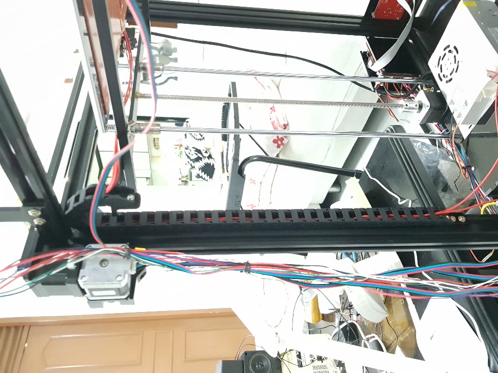
1) Cable chain from heatbed to back of frame:
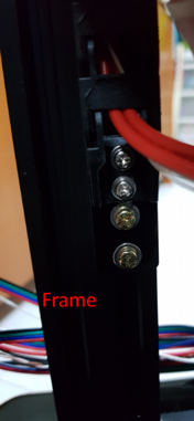
Make sure that both ends are facing the same direction. Use M4 x 8 for the T nut screws and M3 screws for the plastic pieces
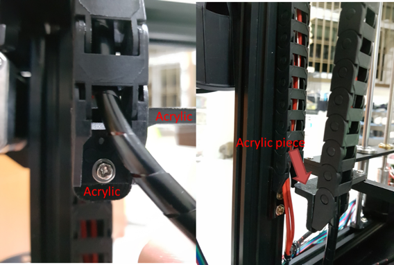
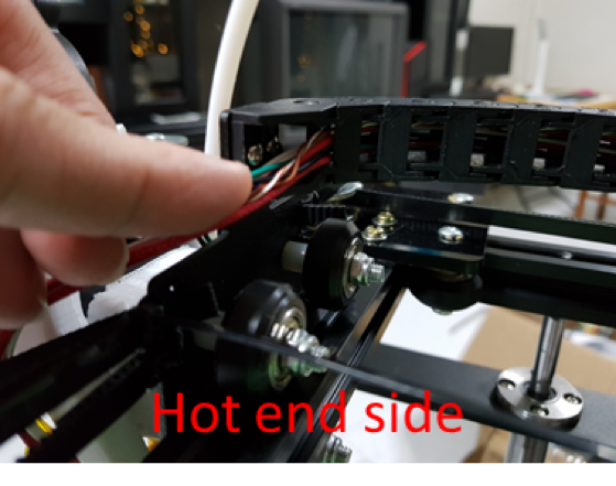
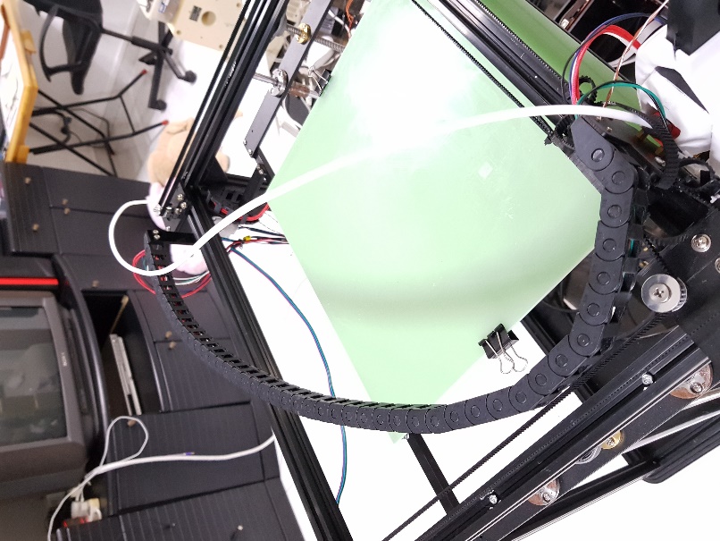
2) Cable chain from hot end to back of frame:

Make sure that both ends are facing opposite directions. Real life photos below!
In the end, the cable chains should end up looking something like this!
Belt setup
Both belts are the same length and GT2, meaning that the pitch between the teeth are 2mm apart. The ones that came with mine had steel wires in them. The belts in a coreXY system have two belt loops running one on top of another, the top and the bottom layers. The top and bottom belt loops are controlled by one motor each, either the X or the Y.
Start by putting a cable tie (red circle) on the lower edge of the metal cutout of the X carriage. Leave a short length so that the belt doesn’t slip off the cable tie. Make sure that the toothed side of the belts are facing each other, and their teeth should be interlocking.
The X motor (on the back right of the frame) drives the top layer of belts, while the Y motor (on the back left of the frame) drives the bottom layer of belts.
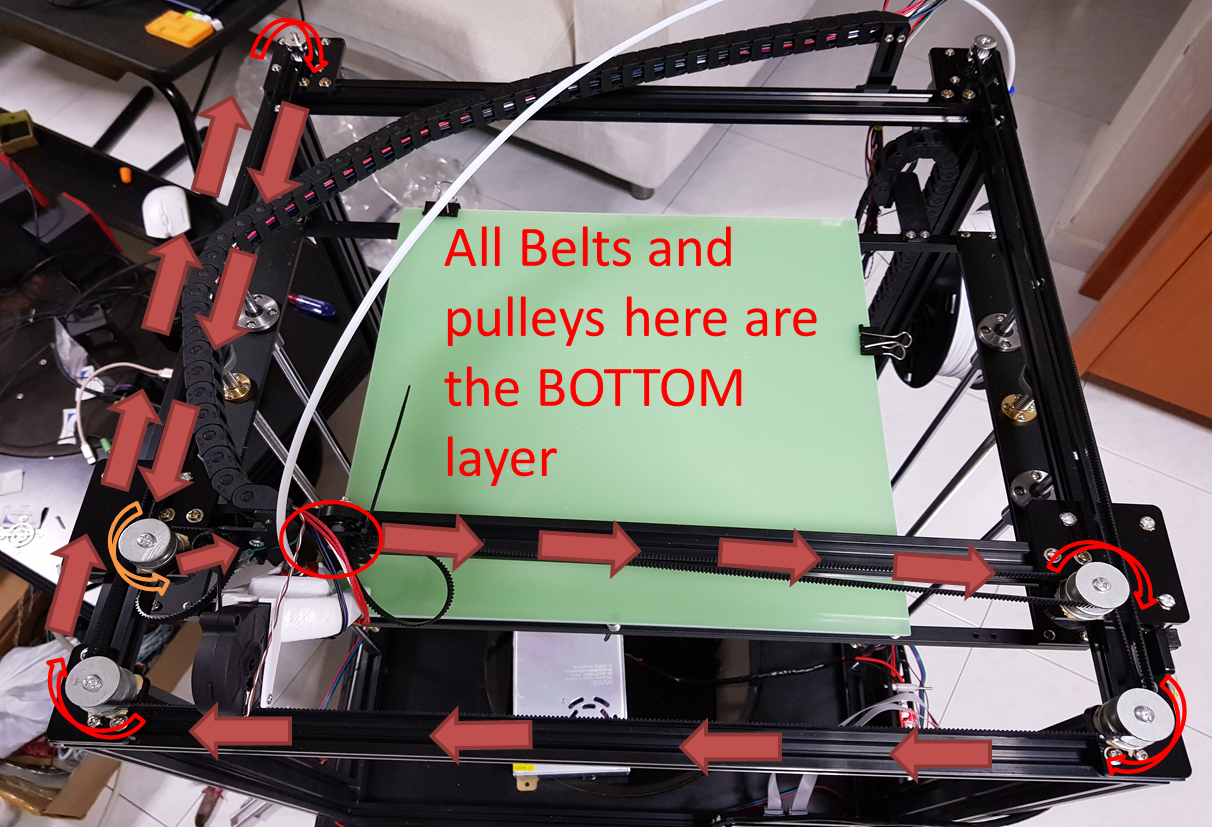
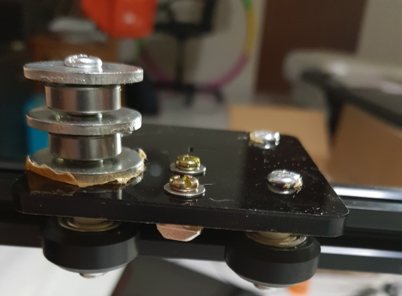
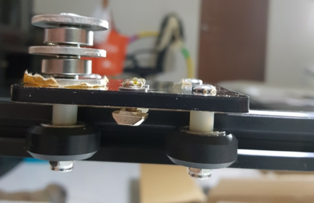
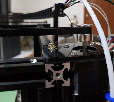
Starting from the right side of the X carriage (as indicated by the red circle – sorry my part cooler fan looks different because I have upgraded it), route the bottom layer of belts as shown until you reach the other end of the X carriage. Make sure that the toothed side of the belt articulates with the teeth of the gear on the stepper motor. There will be one pulley where the smooth side of the belt articulates with it, as indicated by the orange arrow, the rest of the pulleys articulate with the toothed side.
Complete the top layer of belts in the reverse fashion.
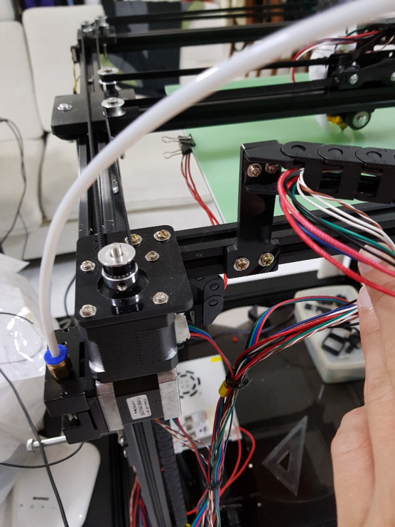
Install the bowden tube – making sure that the tube is fully inserted as deep as possible on the hot end side, as well as the extruder feeder.
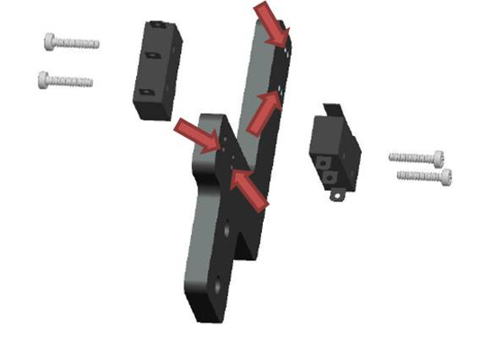
The X and Y limit switches should look something like this:
Assemble the Y (right, facing backwards towards the motors) and Z (left, facing downwards) limit switch. Use the smallest black screws to mount the limit switch to the acrylic piece. I used the holes as indicated by the red arrows. T nuts go in the direction as indicated by the blue arrows (T nut to the left of the acrylic piece, screwhead on the right). Make sure you get the orientation of the limit switch and the T nuts correct. Then attach it to the top front right corner of the frame.
Assemble the Y and Z limit switch. Use the smallest black screws to mount the limit switch to the acrylic piece. I used the holes as indicated by the red arrows. Make sure you get the orientation of the limit switch and the T nuts correct. Then attach it to the top front right corner of the frame.
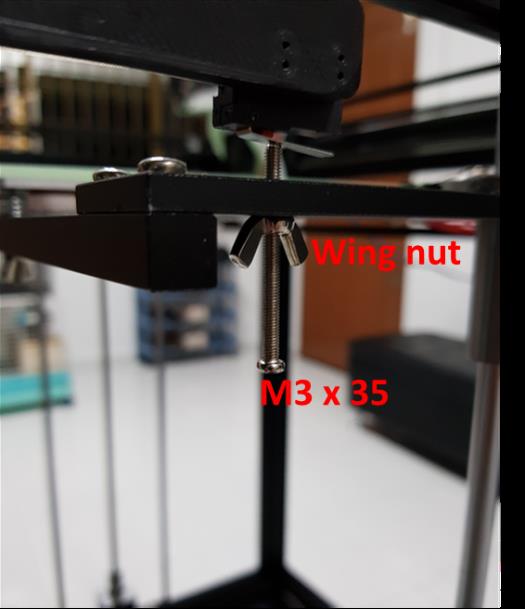
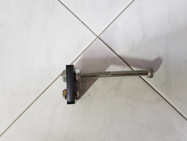
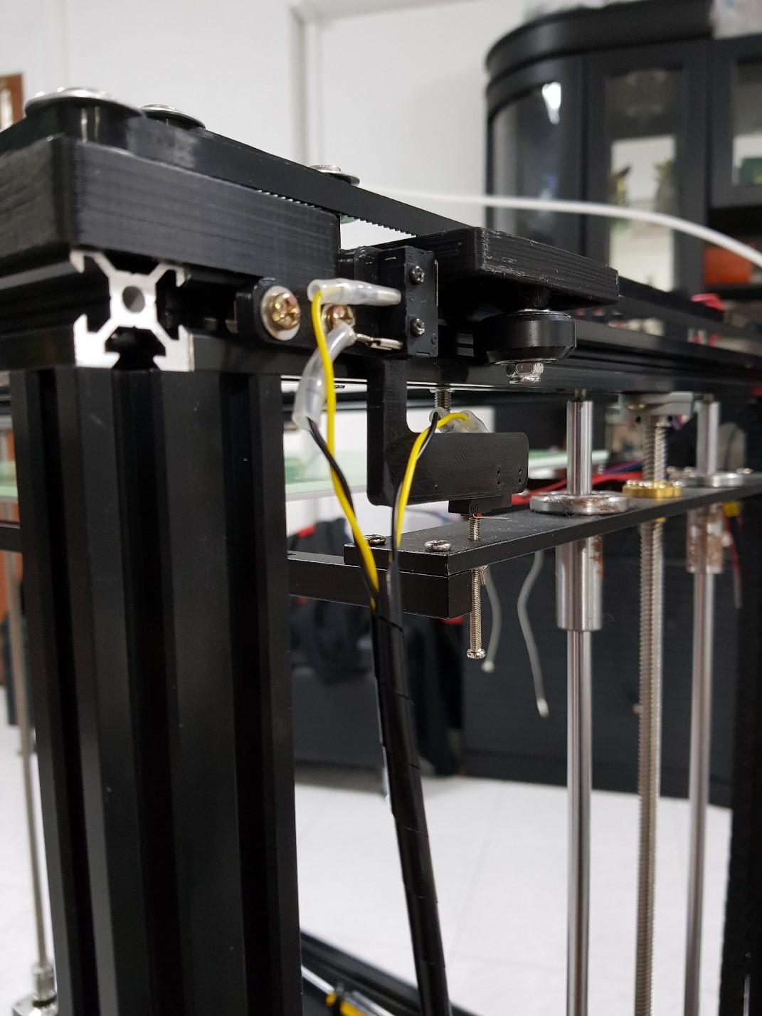
Get an M3 x 35 screw and a wing nut, and thread it through the small hole on the aluminum bar, making sure that the M3 screw can trigger the Z endstop as the Z bed moves up and down.
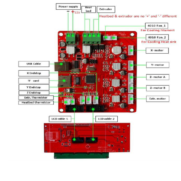
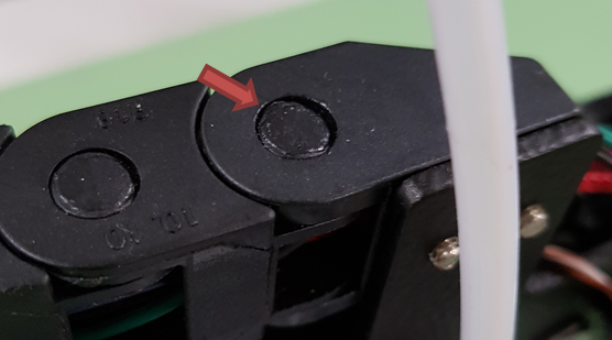
Lastly, wire everything up. The board is well labeled and easy to figure out which wire goes where. Fan 1 is for the part cooling/layer fan (which only turns on when the machine is printing), and Fan 2 is for the hot end heat sink fan (which has to be on at all times when the machine is on). The others are quite straightforward. Red is +ve and black is –ve.
That’s it! You can now test your printer by homing the axes and preparing for print!
Many thanks to Yi Ong for writing this superb tutorial
Tronxy X5S Build Download PDF Version

About the author
Related Posts
Comments 2
