What's New In The 3D Printer World
Stepper Driver Current Adjustment
Well Seeing as How I’m new to writing articles like this and this is the first one I have had published anywhere I am going to take a second to introduce myself a little.
My Name is Scott; I’m 38 married with four kids, and an Air Force Veteran, I have my associates and bachelor degrees. I also have an electrical and computer numeric controlled (CNC) background. I have two CNC mills as well as a CNC lathe and two 3D printers, which is what brought me here.
Over the past few months I have started to see more and more questions about setting up and also tuning various 3D printers and their options. These articles will not be published in any order. They will cover whatever comes to mind at the time that I sit down to write. I tend to write the way I think and speak in my everyday life I am straight forward and NONE of that “you must do things this way”……. I will simply be writing how I do things right or wrong, it works for me and I hope it will work for you as well.
This time I have decided to write about what I consider be a very import part of the 3d printer building stage, but can also be applied to in other it places. It is the stepper driver current adjustment. This is an ever important part of the last stage of any 3D printer build. It does not matter if it is an all in one board straight from the factory or an Arduino mega and a Ramps 1.4 board, with individual drivers on a complete custom build, you at least should be checking the driver’s current. While it is called stepper current what is really measured is the voltage that the driver itself is putting out. What you are actually adjusting is the vref input voltage to the stepper motor driver. This tells the driver what its output current should be. So, you are adjusting the stepper motor current, but indirectly.
There are several reasons that adjusting the stepper driver current is important. If the current is too high the stepper motors themselves will get hot and are more likely to end up in your trash bin, and no one wants that, but on the other side if your current is to low, you will end up with shifted layers in your prints or movements that are inconsistent. If you are having the following issues you definitely need to check the driver current: Hot or extremely warm motors, Shifted Layers in middle of the print, odd pauses or inconsistent.
Now in order to check your drivers, you will need the drivers powered up. Which means you will at least need them plugged into the main board and power supplied to them. Before we move forward you will need a few tools.
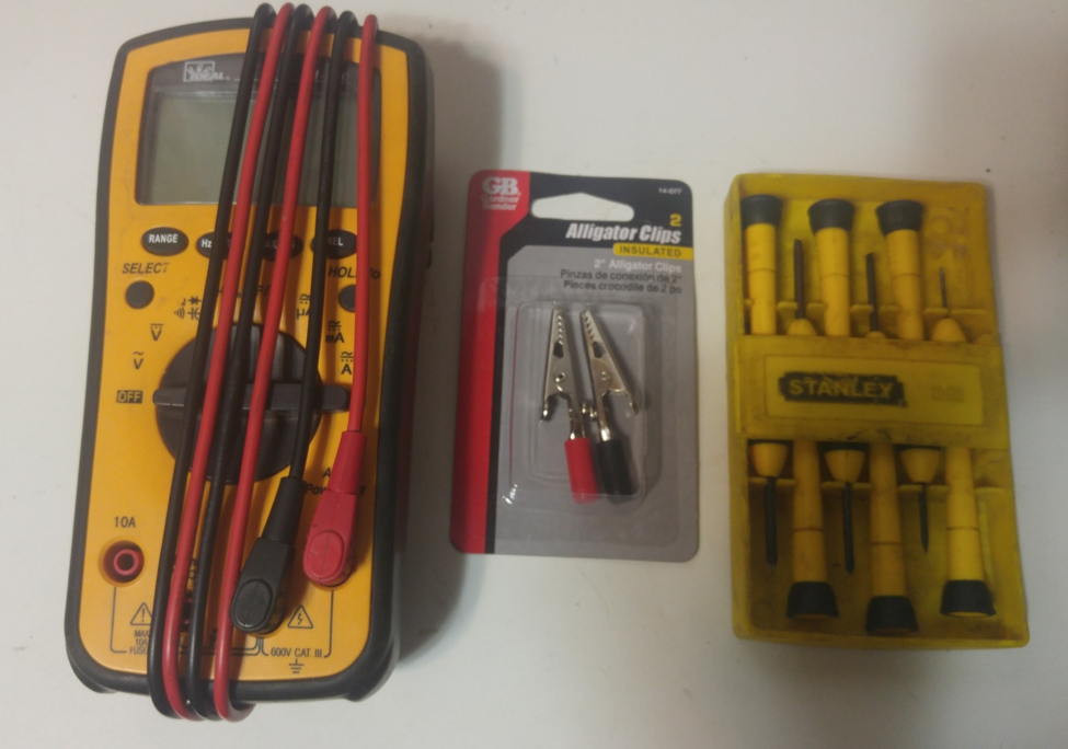
Required tools:
- Multi meter That can measure DC voltage(digital is easiest to use but not required)
- Meter leads (with clamps would make this easier but once again not required)
- Small flat head screw driver with plastic or rubber handle
With everything laid out it is time to locate the stepper drivers on the different boards. I will be giving you examples on a few different boards. One is an Arduino ramps combo board, then I have the factory board from my Tronxy X3 and the Tronxy X5S boards. Not all boards are the same but most will tend to have the same layout and general look so you should be able to find what I’m talking about on your exact setup.
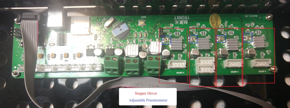
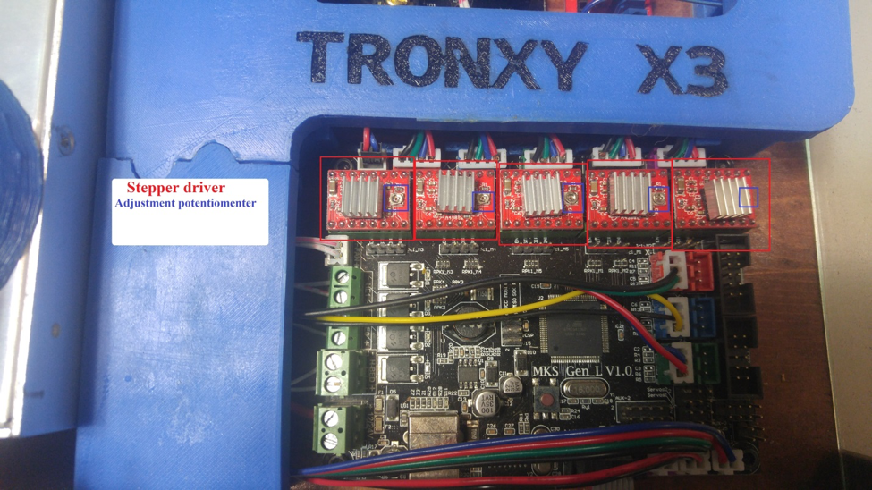
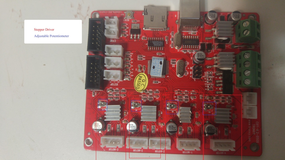
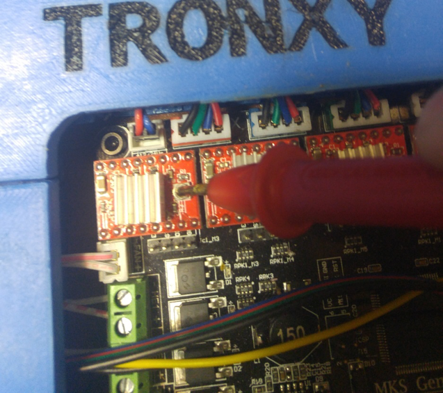
Now in all of the pictures below I have marked each stepper driver and it’s adjustment potentiometer so you can see the layouts are basically the same. The first two boards I have with the stepper drivers are built onto the main board itself. The bright red board is from my Tronxy X5S printer. The long green is board out of my Tronxy X3, and the square black board is an MKS Gen-L control board with A4988 stepper drivers. I then included a picture of an individual stepper driver that’s not installed on any control board. 
Now let’s get into more detail and find the current adjustment potentiometer for one of them.
Once we have that located the next thing is to get your multi meter ready, turned on and set to DC volts. (See note 2) We will be checking from 0-24 volts DC so make sure that is what it is set at. I recommend that if you have a clamp for the end of your meter leads you should to use them on the ground side (black wire). Now hook this to the main ground wire. Let me just say that (really any ground on the board should work as they are normally connected) but for ease this time let us stick with the main ground.
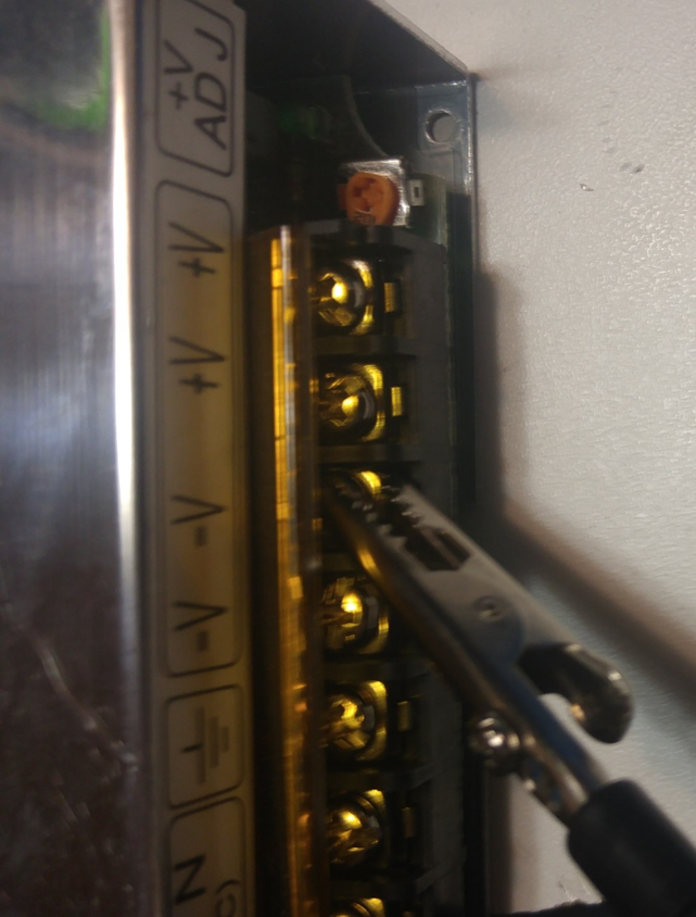
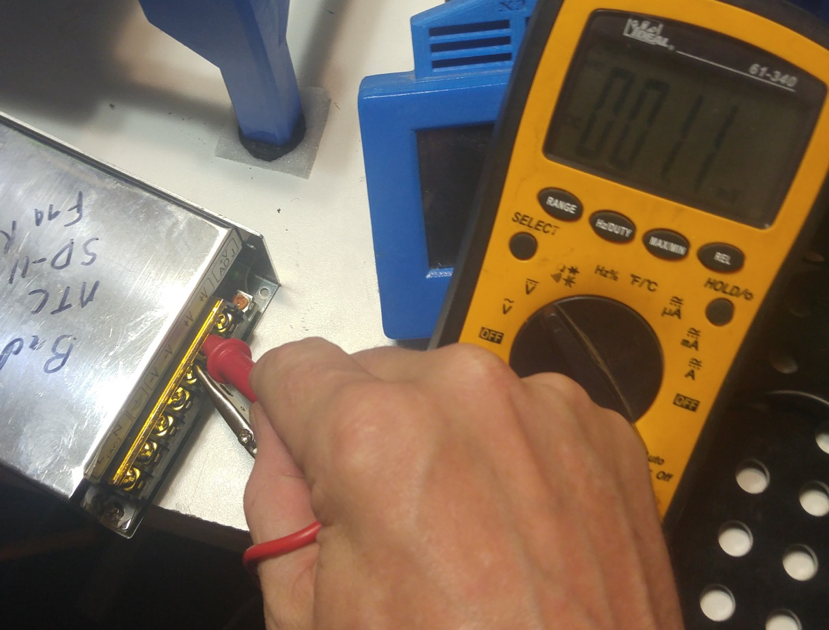
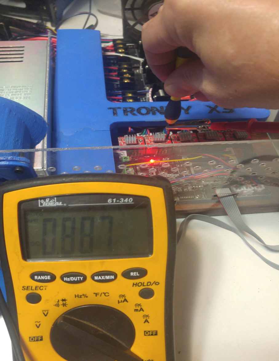
Power up the control board. To start with I check the incoming power to the control board. To do this hook the clamp end of the black wire on the power supply ground then take the red lead and touch to the positive side of the incoming power either at the power supply like I did in the picture or on the control board itself. Now if you are using a 12 volt power supply then this should ready 12-13 volts normally. This also insures you have a good connection at the ground and your meter is working correctly.
(For pics I used a spare power supply that’s why there are no wires hooked up)
 .
.
(Again spare power supply… this one is bad as you can see by the note on the top, LOL)
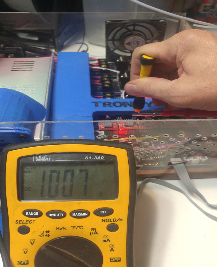
Now to check each drivers output current (voltage) by touching the red meter lead to the potentiometer itself. Careful not to touch anything long the way. Personally I write a list of each driver I’m going to test and the voltage I get for each one as it comes from the factory.
I have found that the board can have a wide range of voltages from the factory and while they might work most of the time these settings are not ideal. Point in case the factory control board for my Tronxy X5S came in with voltages from 0.789 to 1.319 volts DC. Based on what I have read most of the time the recommended voltage is from 0.9 up to 1.2. This is where I’m going to tell you I use a little different settings and this as just my personal setting and is not set in stone, set them how you want. For the extruders drivers I set them from 0.9 to 1.1 because I have found the motors get warm when set to anything above that and I have not had the motors skip or miss steps. Then for the rest of the drivers I set to 1.1 to 1.2 volts DC. NOW IF the driver is pushing TWO motors such as is the case with both my Tronxy X3 and the Tronxy X5S Z axis, I will turn the voltage up a little further because it is split between two motors I tend to go 1.2 to 1.3.
The factory suggests the use of a porcelain tipped screw driver for adjusting the potentiometer. I do not own one and would not use it in this case but feel free to if you would like, it will just add a few extra steps in the adjustment. If you use the porcelain tipped screw driver you will have to adjust a little then check voltage then adjust then check and rinse and repeat until you get the voltage you want for each driver.
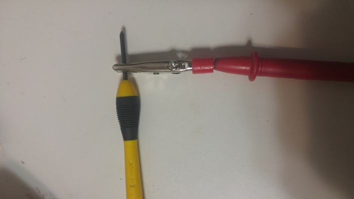
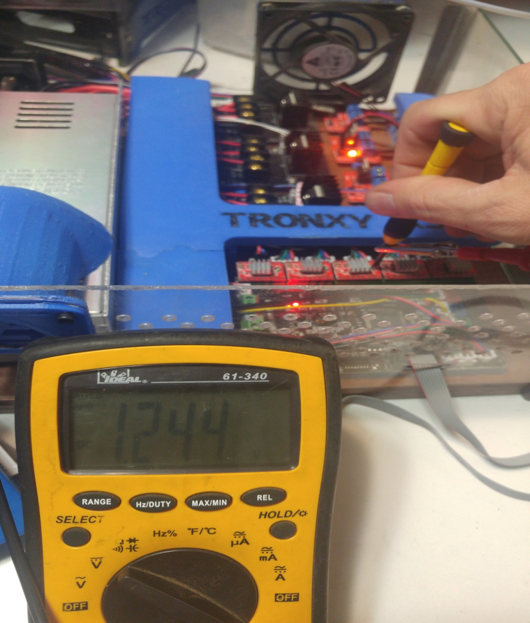
If you have a clamp for your red multi meter lead this is when it will come in handy otherwise you will have to do it the same as if you had a porcelain tipped screw driver. Attach the red lead of your multi meter to the metal shaft of your screw driver. Make sure the screw driver fits the potentiometer correctly so it will turn the adjustment part rather than just spinning on the top edge or the point resting in the center not turning it.
BE GENTLE FOR THE REST OF THIS OR YOU MIGHT BREAK THE DRIVER AND YOUR BOARD……… Now carefully reach the screw driver in to touch the top of the first potentiometer you wish to adjust, this does not take a lot of force at any point. Make sure not to go bumping the screw driver around against the rest of the board. Once the screw driver is in place all you need to do to turn the voltage up simply turn the potentiometer SLOWLY counter clockwise, to turn the voltage down turn the potentiometer SLOWLY clockwise. Now it is best to move the potentiometer very small amounts then give it and our meter time to catch up and check the new reading. DO NOT FORCE THE POTENTIOMETER TO TURN it should turn easy if not it might be maxed that direction so try the other way. Remember to watch the meter and stop near your goal voltage. Once you reach your goal voltages you are done with that driver simply move on to the next one until they are all complete.
Now once this is done and you have your printer up and running. Make sure to feel your motors with your bare fingers if the motor is warm that’s ok but if you touch it and you want to pull your hand off because it’s HOT then you need to turn down the drivers current, and that is why I recommend writing down your settings when you first check and then what you set them to. Then if the motors are not getting warm or missing steps your good to move on to other items like tuning the printer and which we will more than likely cover in upcoming articles. Feel free to let me know what other articles you would like to see.
Have a great time… Enjoy your time Life is short.
Until next time
Scott

About the author
Related Posts
Comments 19

Odd I will double check mine been a while sense I have actually done it other than on the spare board I use in the pics for this write up...LOL Thanks for the comments... feel free to join and help get the forum active... there is a downloads area and video an photo section that only forum members can see as well.
From some other site:
Q: How hot is too hot to run a stepper?
A: Stepper motors are designed to run hot. Most have class B insulation which means they can sustain temperatures up to 90 C without thermal breakdown occurring. This breakdown comes in the forms of insulation and winding failure.
But there is another problem with overloaded motor, more serious than the hot motor:
Q: Is it true that I can get more torque by running the motor at double the rated current?
A: Increasing the current will produce more torque but there is a cost. The motor will not run as smoothly since increasing the current hinders the motor’s linearity.
So I just did a web search on "3D printer how to set stepper current" and up you popped. By the way, I checked my stepper settings before I adjusted them, and my X & Y steppers came factor adjusted at .8 VDC. I upped the values per your suggested values and so far so good on a print of some corner braces.
Right now, there seems to be a slight ripple in my prints at sharp edges in both the X & Y axis. So I've installed some corner brackets (Just Printed after stepper current increase!) to further tighten up the frame. Next, I plan to run some resonance tests to see if I I can improve things by optimizing the max acceleration and max jerk values.
On my Tronxy X5S these stepper driver potentiometers were incorrect adjusted. Because i don´t have any equipment to measure stuff, i could handle it by testing the torque of the motors by putting resistence with my fingers on the motors. It worked pretty well !!! You just have to get minimum torque, which is better as higher (if not needed). This was my solution to get them right.