What's New In The 3D Printer World
Tronxy X5S to X5SA Upgrade kit installation
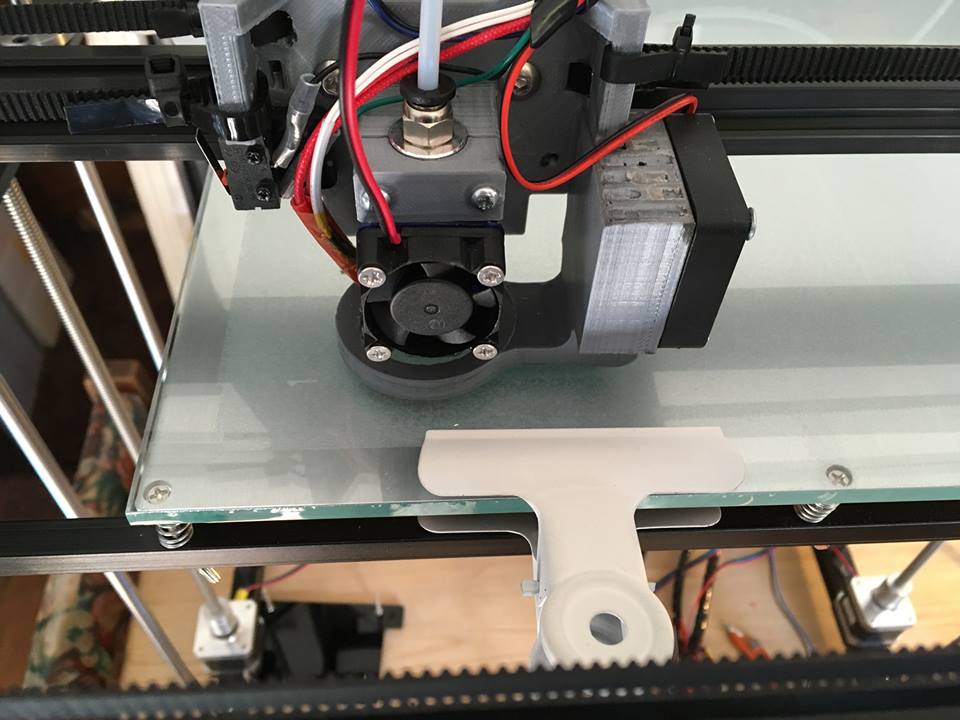
OK Scott Here again like normal. This time I had a little help from Norman Gilman with some pictures and a few of the steps, helping to get my mind in gear to write this. Now please note Neither Norman Or I installed these setup with the auto bed leveling because we use glass beds to thick for the factory blue sensor to see the bed through the glass.
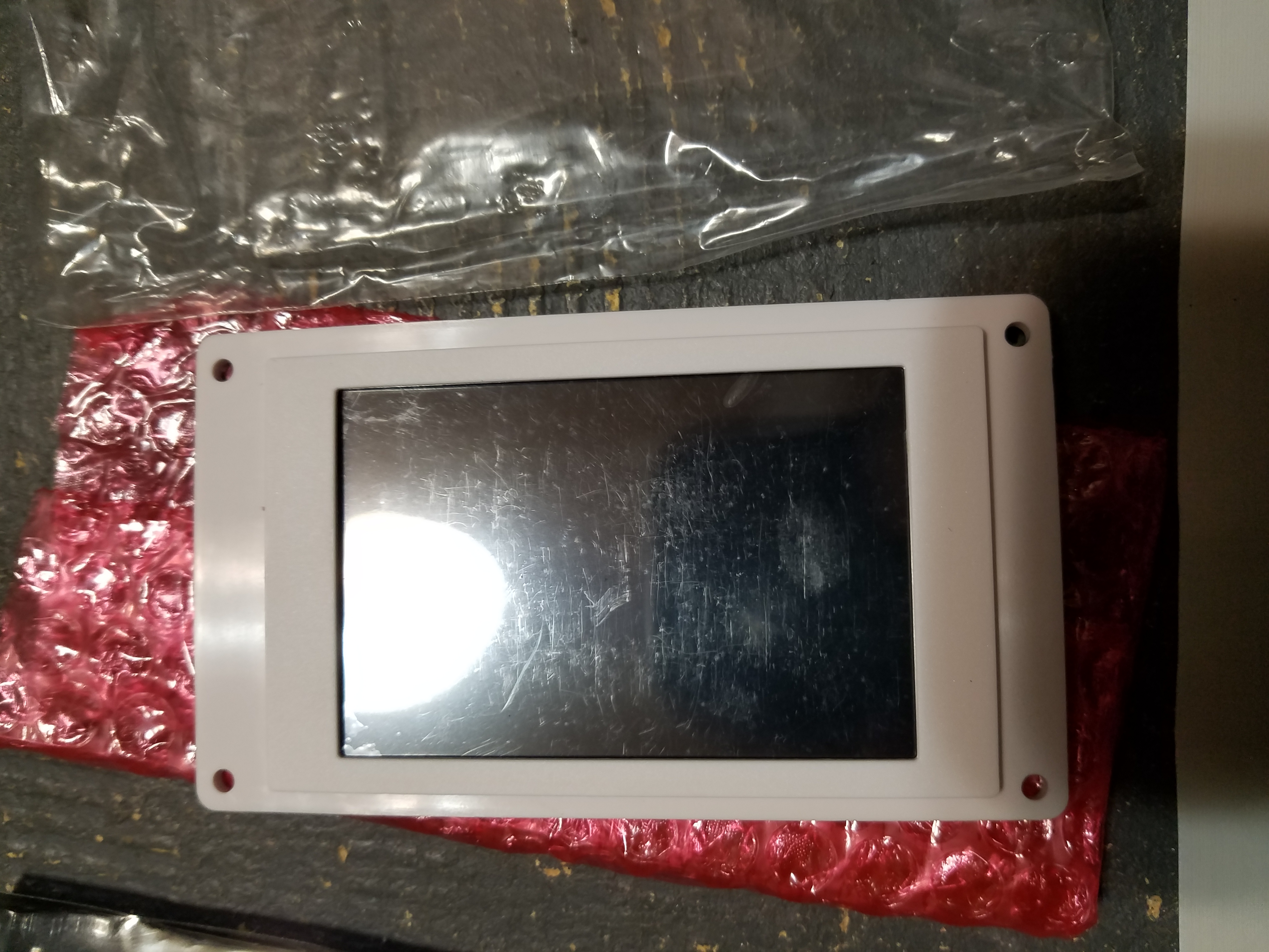
Let’s start out by showing exactly how my Upgrade kit came in From Tronxy. 

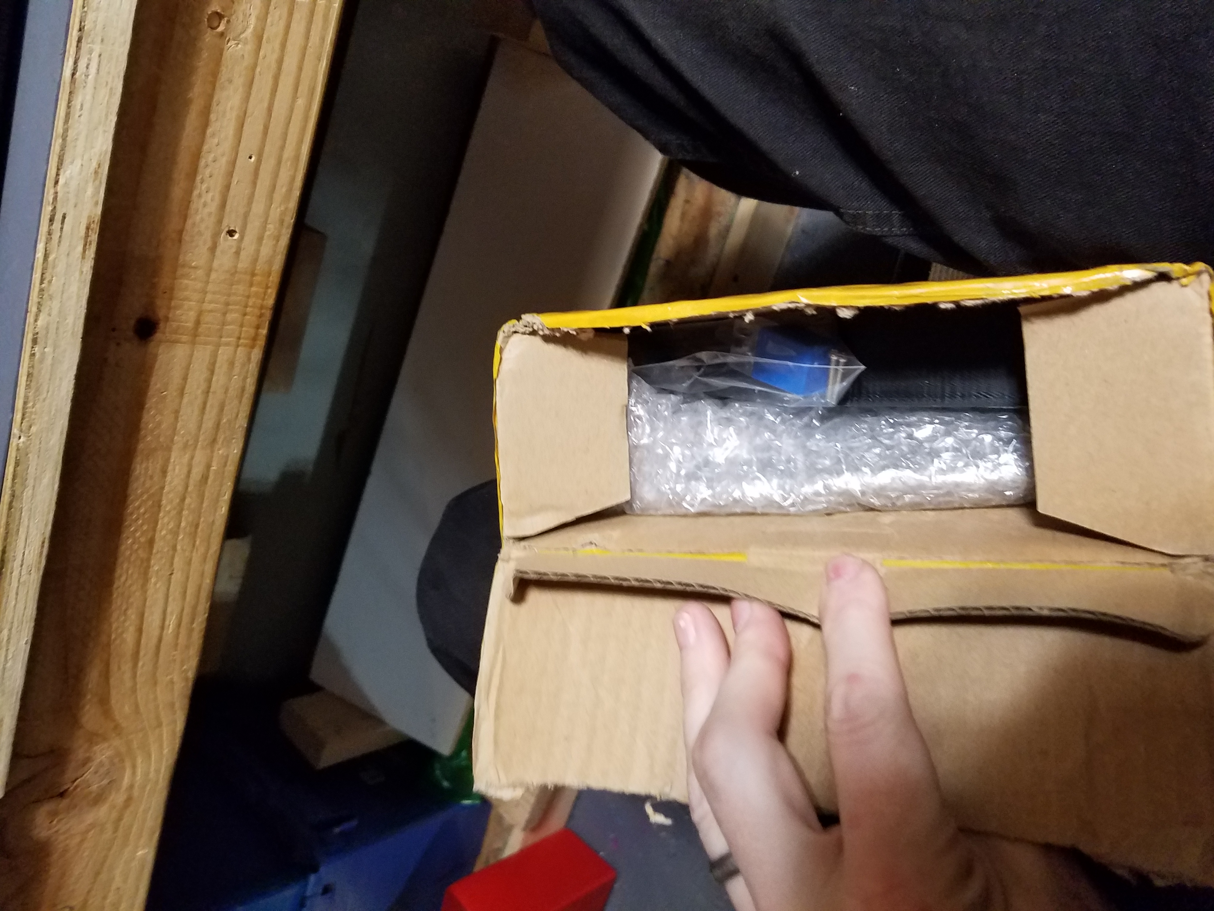
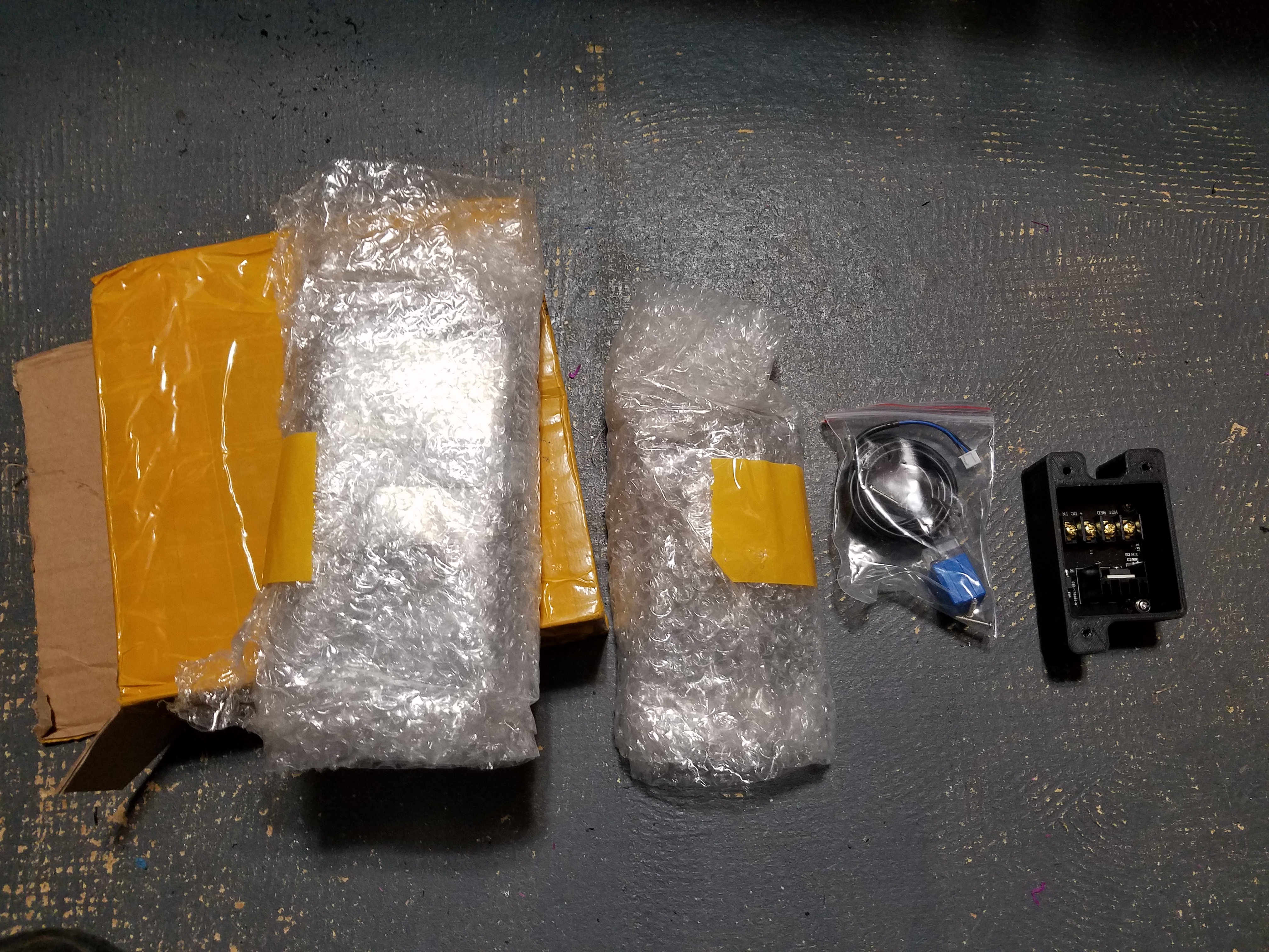
Not bad packaging in this case. So Time to see what all is hiding in the bubble wrap. Laid everything out just to see what all was ahead of me.
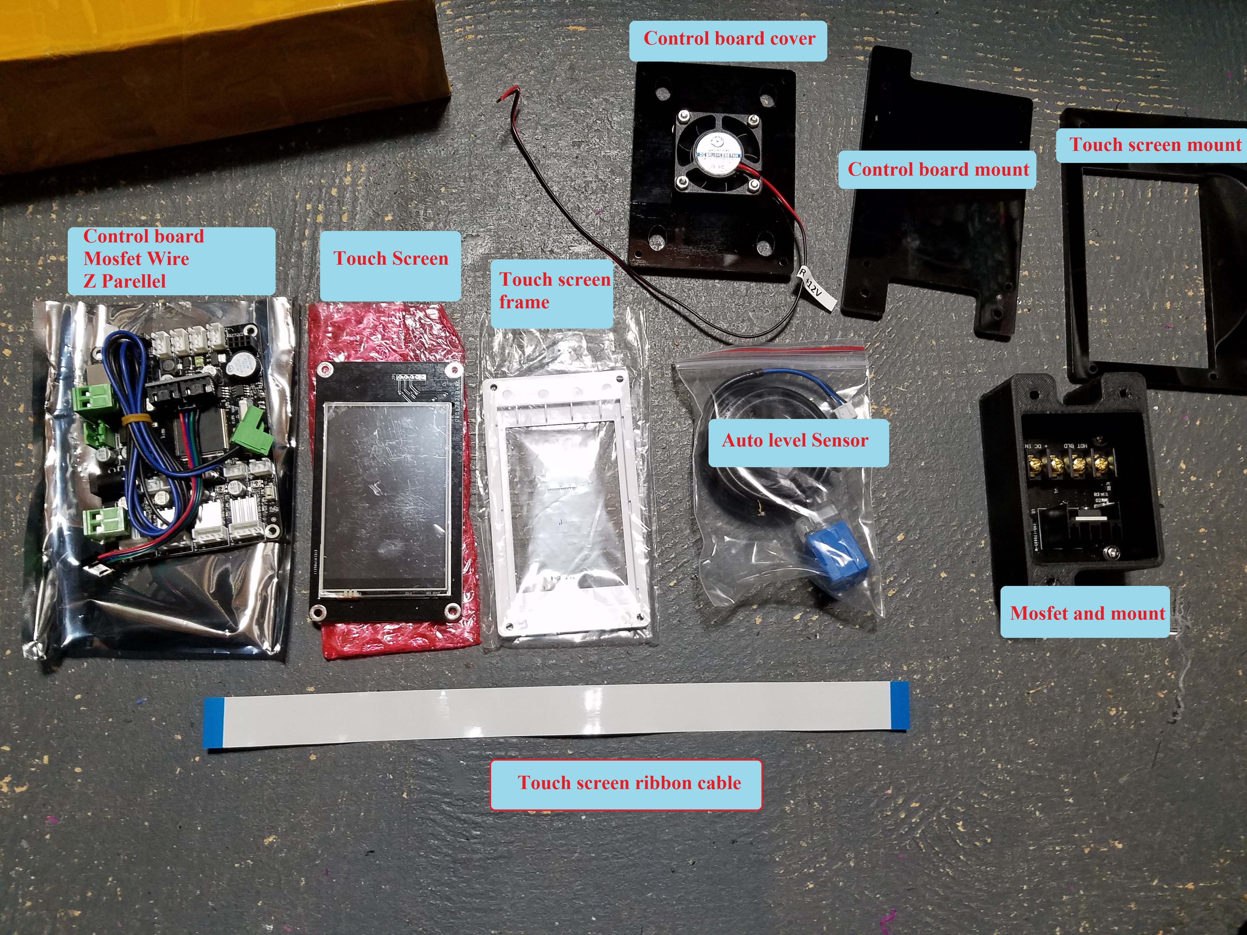
Not because this Kit does not come with any hardware you can either remove the Factory X5S screen and control board, now to use the hardware not or do it once the wiring is swapped over. I would recommend removing X5S screen and control board. To make it easier to get the hardware installed.
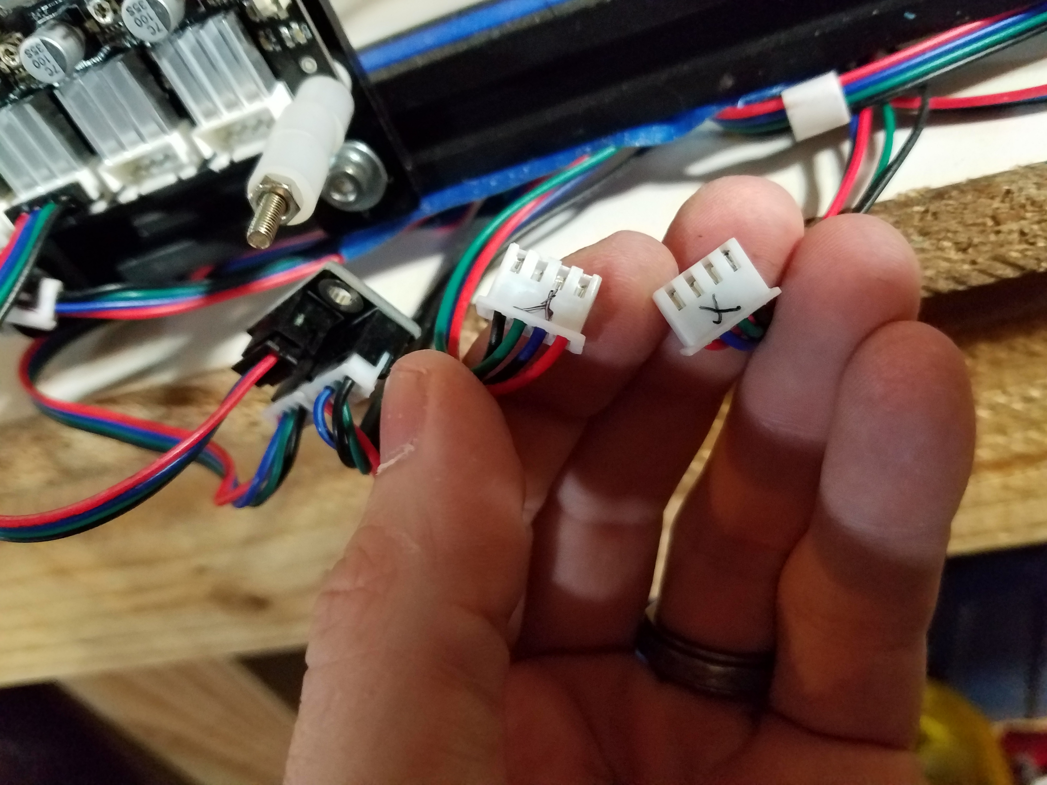
Now here is a tip to save you some headaches. Mark your wires and plugs.

Time to start putting this together. I started with the screen (protective cover still on my screen)
Make sure when you put the touch screen frame on the touch screen that you put it so the holes will line up.
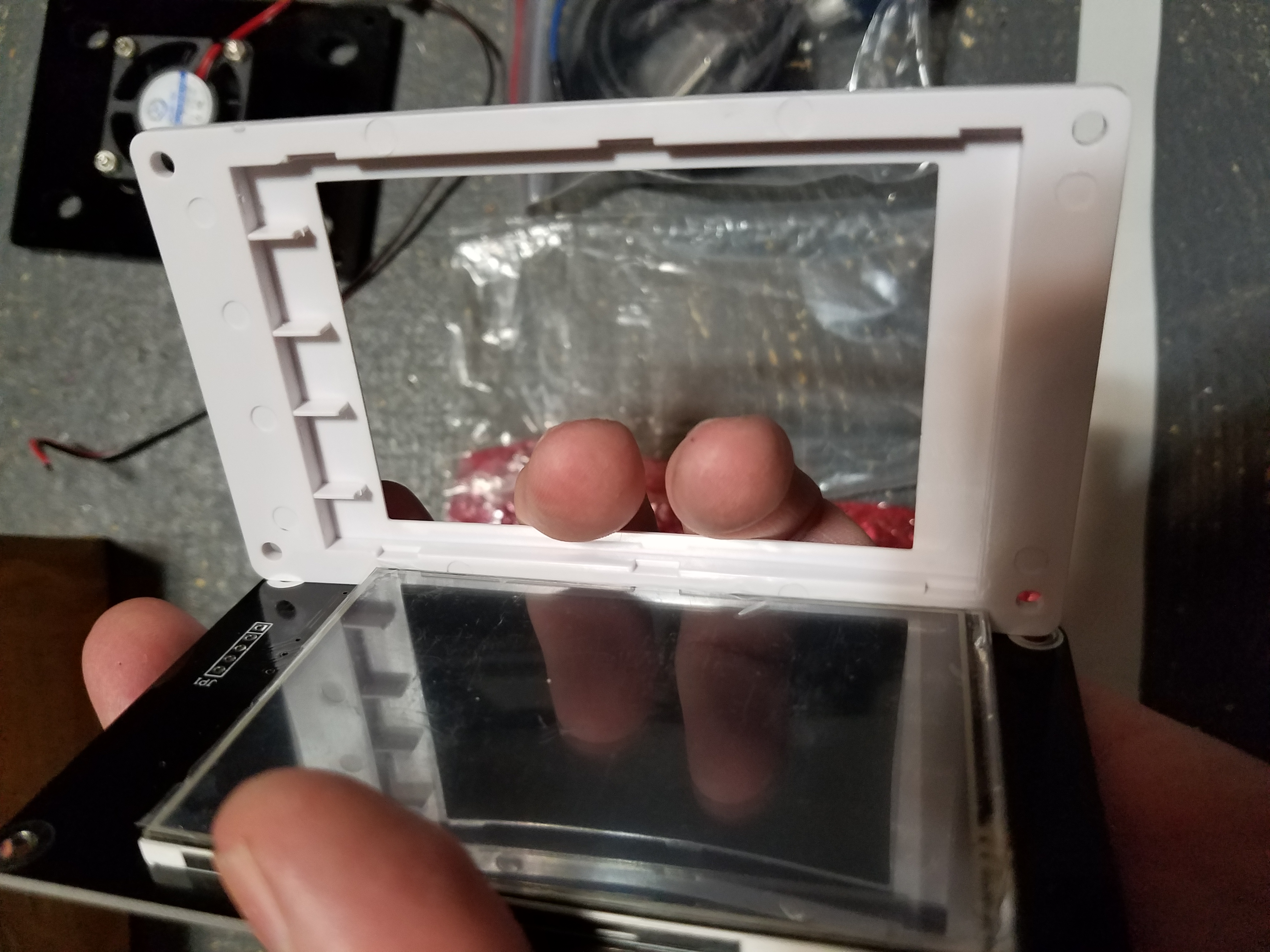
Time to put together the full screen system by attaching the touch screen and frame to the mount. Use the bolts off your factory screen to mount this together. At this point you can go ahead and put the M4 bolts and T nuts on the touch screen mount so you can mount it later. Set the screen aside 
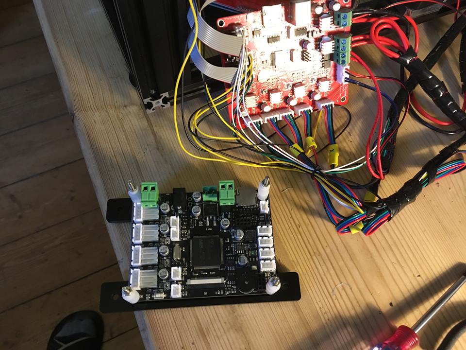
Mount the new control board to the new control board mount. Take care to use all the same spacers in the same places.
Note in this picture I have installed all the spacers and the Z parallel adapter. ( I also mounted mine different so make sure for a factory setup you have the SD card facing upwards)
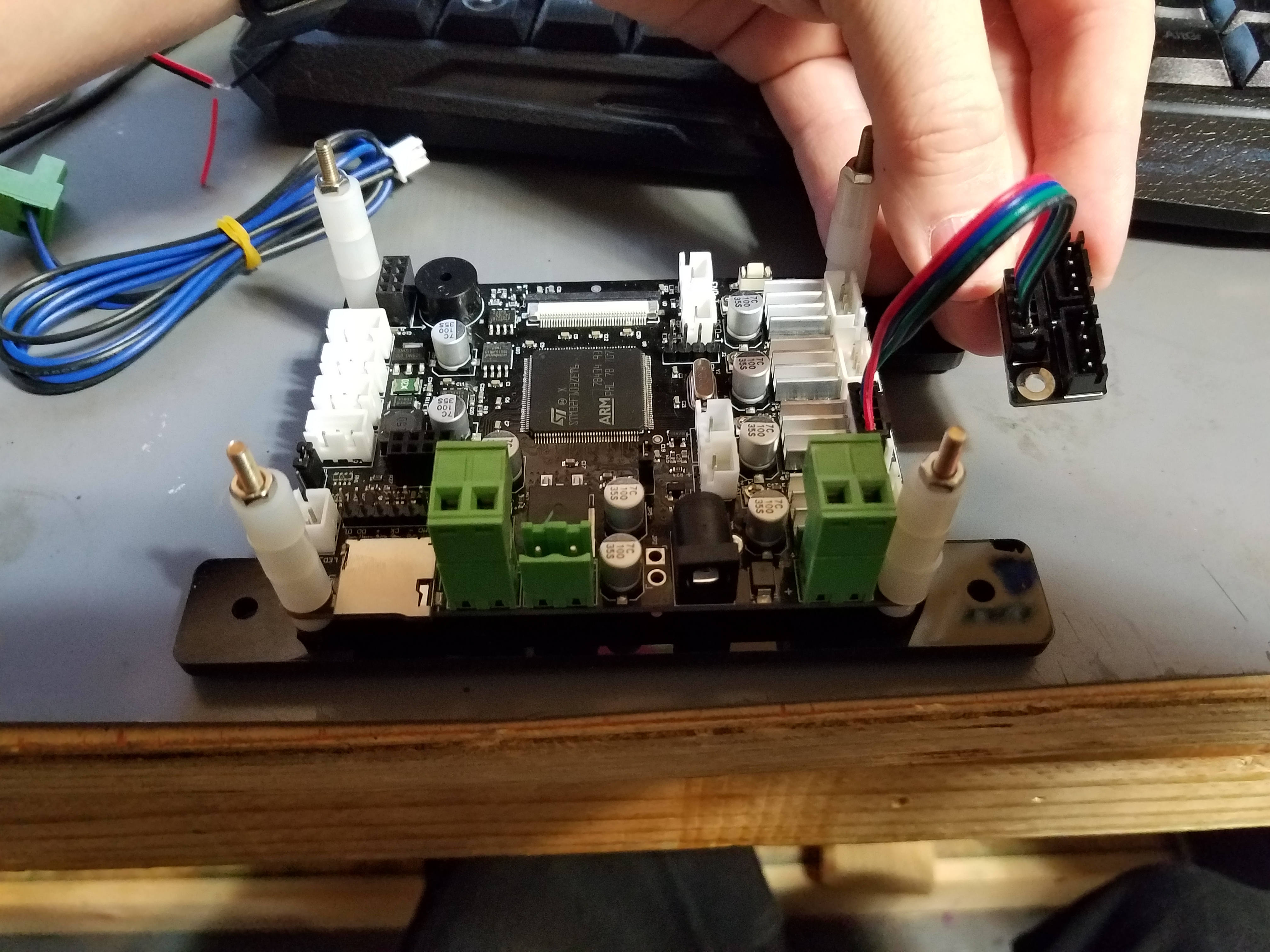
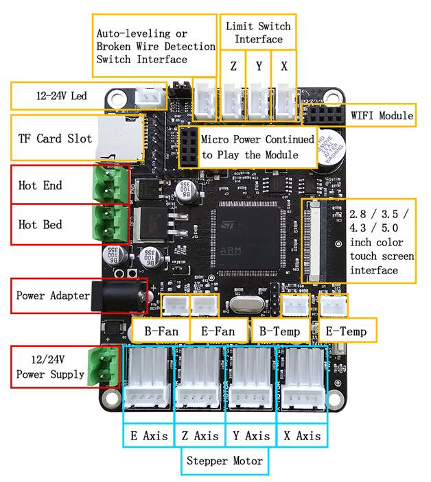
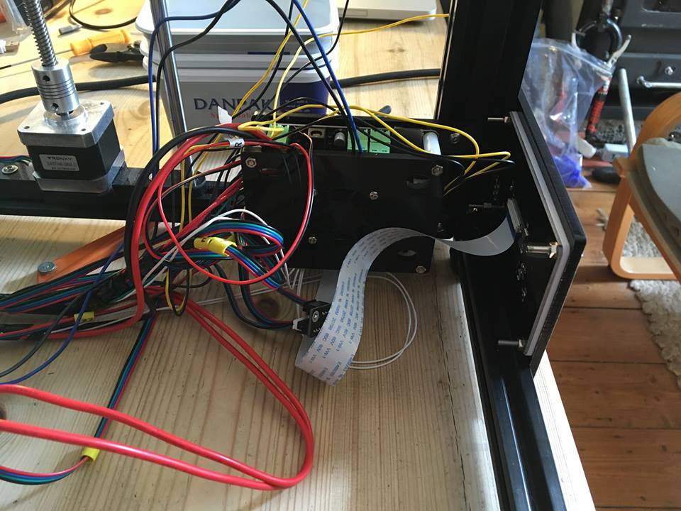
Now the fun begins Swap in the new control board.
Screen ribbon cable slots in writing facing board (carefully lock into place with black plastic latch and gently test with a tug to check it is locked in).
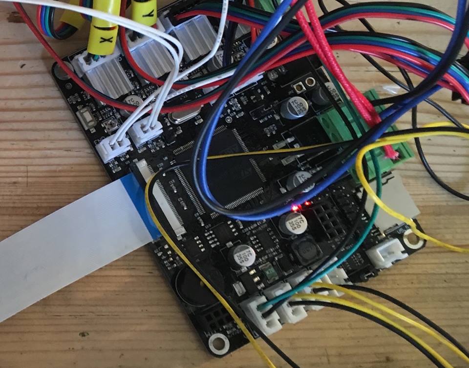
Same at display end.
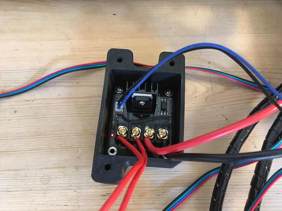
Connected MOSFET thus (heavy gauge black and red wire are from PSU). Red wires off to bed. Black and blue wired plug from BED socket on board. Small red LED indicates power to MOSFET is correctly applied. For this I use 12 AWG wire (wire not provided in Kit)

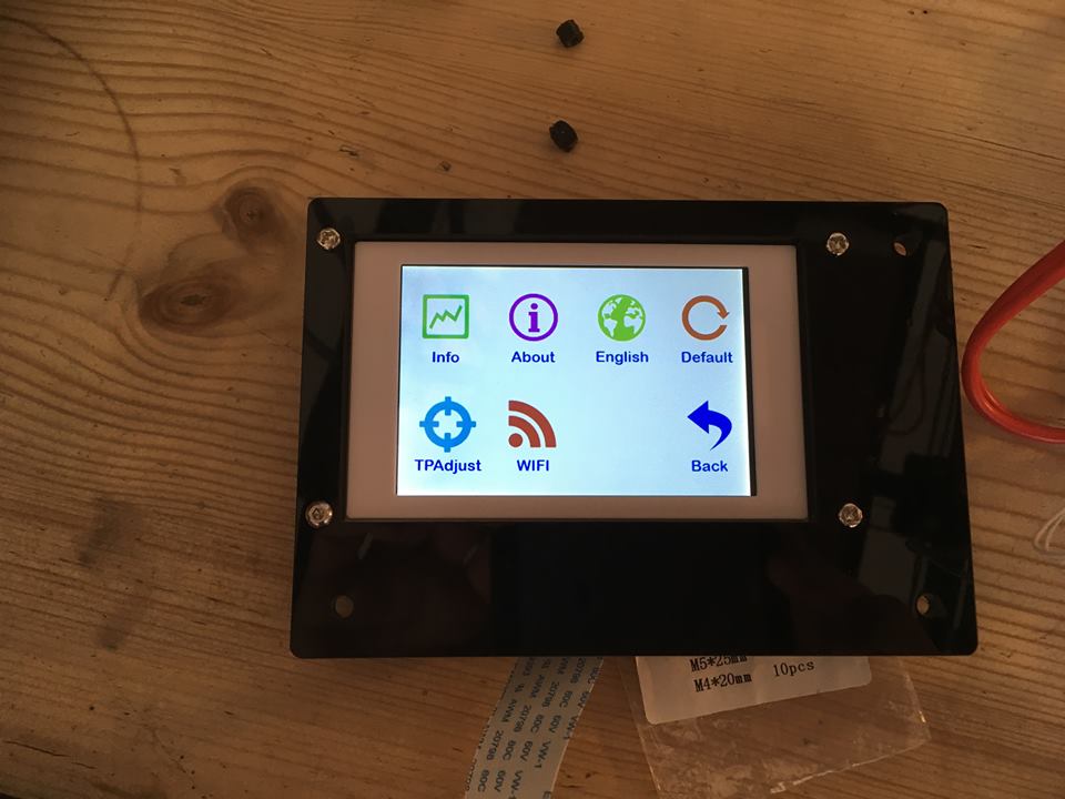
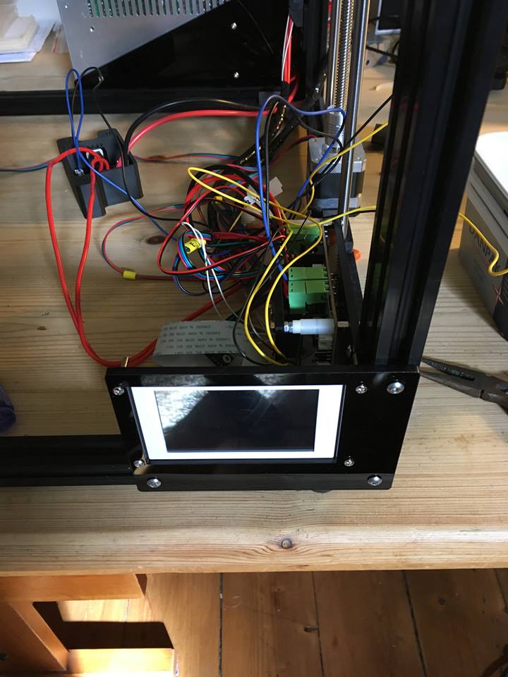
Power up after thoroughly checking everything and navigate around the menus. This is the SYSTEM page.
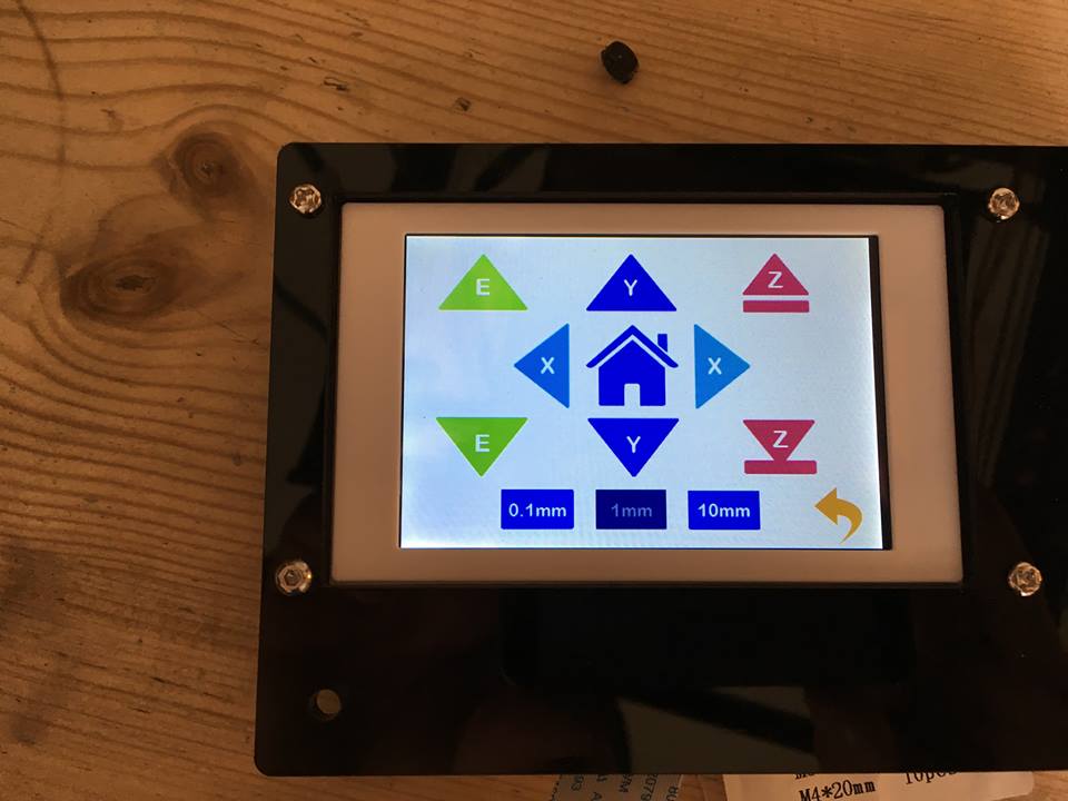
In the TOOL page you will find a MANUAL icon. Tapping this brings you to the manual driving arrows and the HOME icon in the center. DO NOT hit this until you have run the no-level .gcode. I buried my hot end in the glass bed as it didn't recognize z-stop until I did that. If you mount the auto level sensor there is no need for the non-level gcode file.
Test MOSFET operation by navigating to the PREHEAT menu (also under TOOL icon). Tap icon for bed preheat (a small bonfire icon!!!) I think there are a number of preset bed temps on here. Successive taps on other arrows changes temps (Thermistor measured temp is on the left, target temp on the right). Small blue LED indicates bed element is heating.
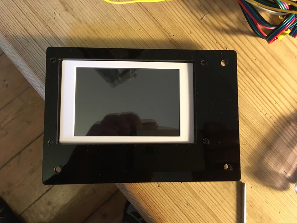
Once you know things are running right install board and screen into similar spots on frame as before (Norman moved the board mount inside frame to clean up the wiring outside).
 Tested out the autohome after running no-level.gcode. 3 scary loud beeps later it sat in its proper place.
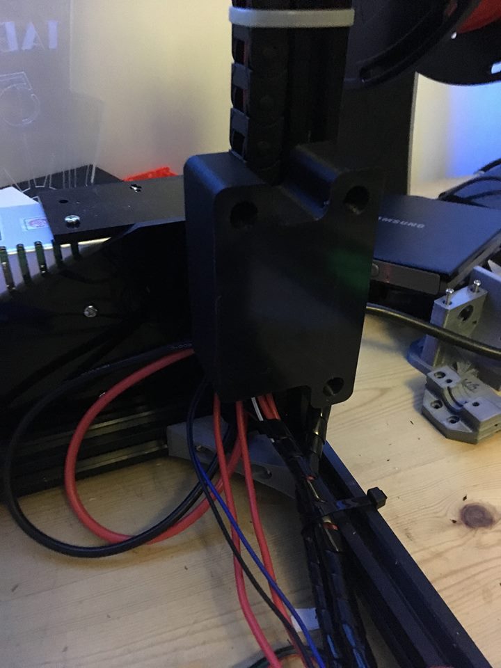
I fitted the MOSFET case next to the cable chain mount. It's not brilliant and could do with replacing. The MOSFET PCB mounts were crap on mine and 2 of them snapped off as I screwed into them.
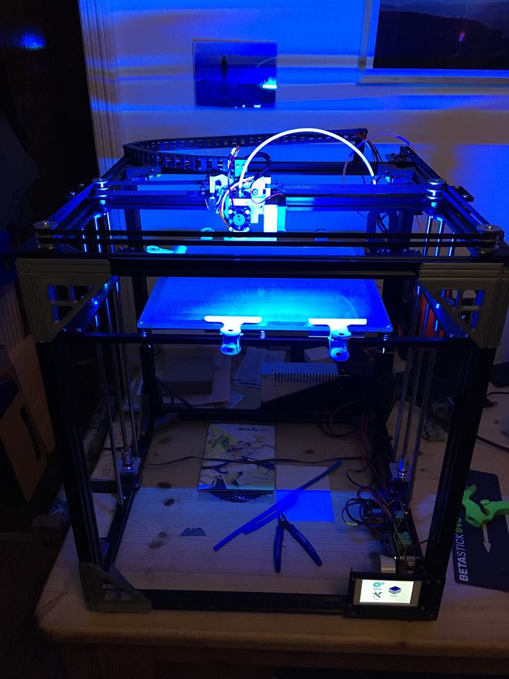
Et voila. Nasty blue light comes from LED running lights. There is a handy socket for a 12V LED strip on the board.

In the end find what works for you and run with it. Sorry no auto level setup included in this article I don’t use it. I will be uploading the G codes here as soon as I get them finished. Until then you can read up on the G code this control board uses to adjust the firmware. I just finished the article on it here... here
If you want to get one of these kits you can only buy them Here.

About the author
Related Posts
Comments 6

So I completed the Upgrade last night I turned on the power had the touch screen was working well. turned it off and now i turn it on and i get the beep the hotend fan runs for about a second then it stops and nothing comes on. Anyone else seen this or advice on what I did wrong?
I am using a 24v PSU I also tried it with the voltage step down to 12v to the MOBO and same thing.... UGH
Ordered and received X5S to X5S-A
upgrade kit. (order#D6A8087).
Need information on the installation. The info on your site does not describe the kit I received. There was no MOSFET module; only an acrylic bracket. Specifically I cannot tell from the information on your site how to install the height sensor. I appreciate the fact the it came with a new control board and display. I'm also assuming that the proper firmware is already installed on the new board.
Thank you.